
Connection strength testing device

Inactive Publication Date: 2010-02-04
HONG FU JIN PRECISION IND (SHENZHEN) CO LTD +1
View PDF0 Cites 0 Cited by
  • Summary
  • Abstract
  • Description
  • Claims
  • Application Information

AI Technical Summary

Benefits of technology

[0004]In manufacturing, two articles are often connected by adhesives or soldering, for instance, rubber pads are adhesively attached to a base of a notebook computer to providing support therefor. Strength of the connection between the pads and the base may then be tested by use of a thrust meter. An operator forces the thrust meter to exert a predetermined force on the connection interface between one of the pads and the base for a certain time. However, it is not only that the testing procedure is inconvenient, but also that it is hard to get a stable and accurate connection strength value because of vibration or movement during the test.

Problems solved by technology

However, it is not only that the testing procedure is inconvenient, but also that it is hard to get a stable and accurate connection strength value because of vibration or movement during the test.

Method used


Image

  • Connection strength testing device
  • Connection strength testing device
  • Connection strength testing device

Examples


Embodiment Construction

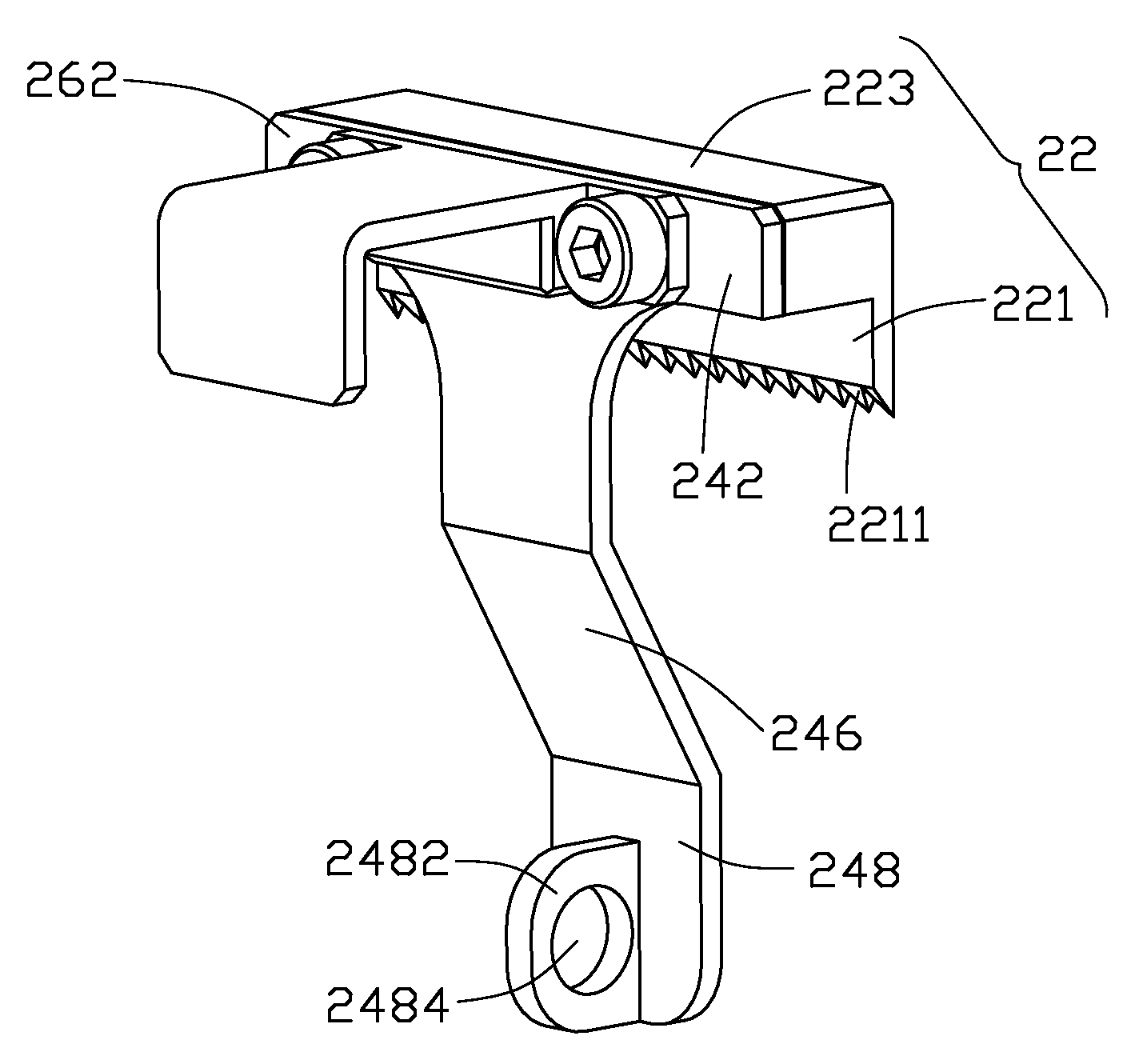
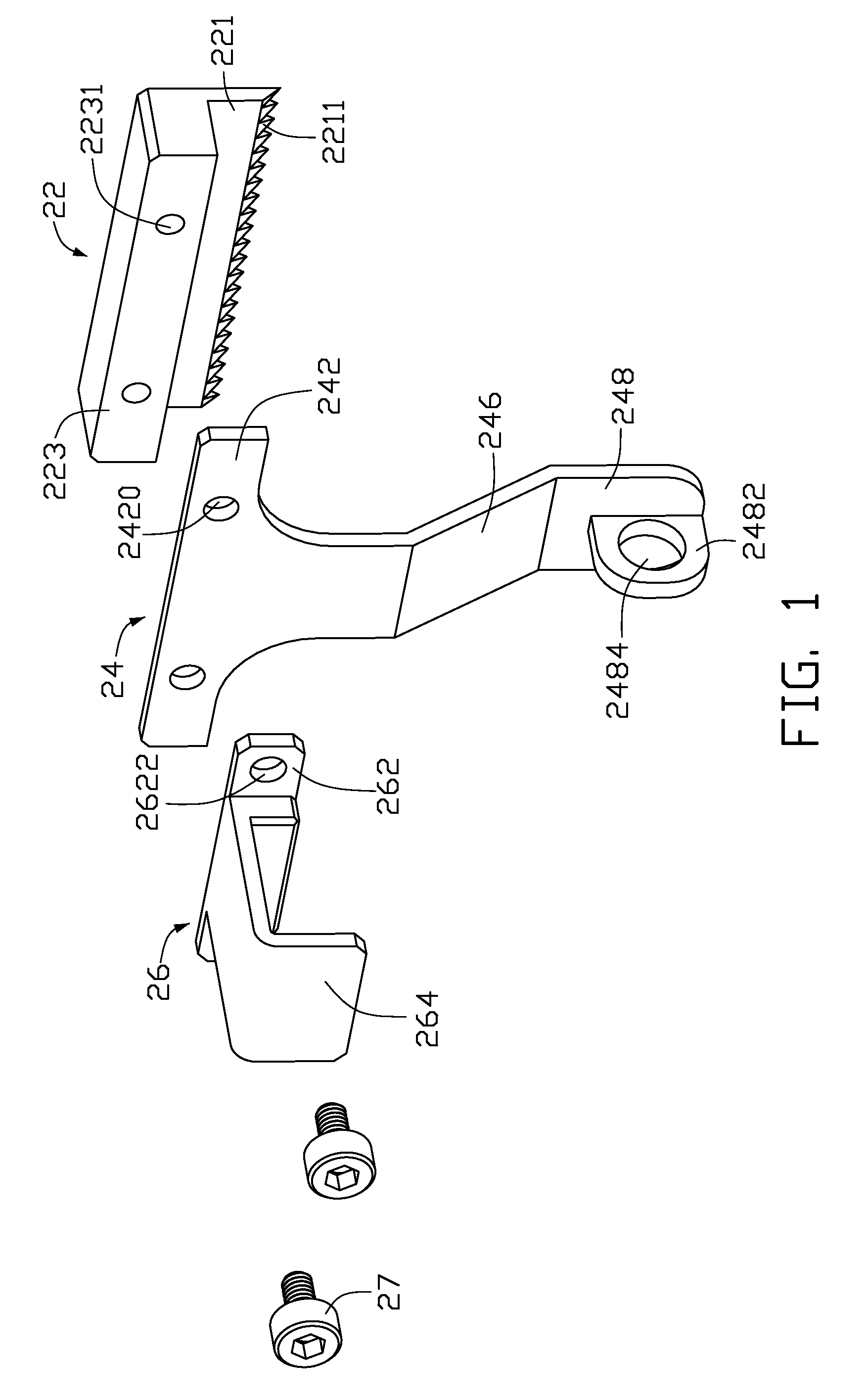
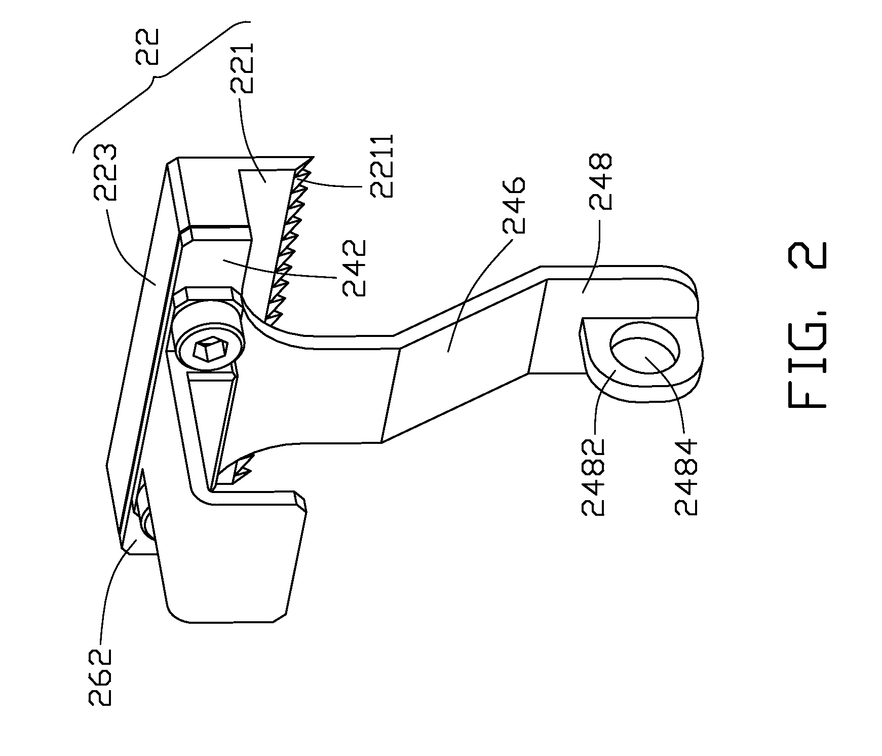
[0009]Referring to FIGS. 1 and 3, an embodiment of a strength testing device for testing a connection strength between two articles 101, 102 is presented. The test device includes a blade member 22, a suspending member 24, and a handle 26.

[0010]The blade member 22 includes a blade 221, and a protruding portion 223 extending perpendicularly from the blade 221. A plurality of teeth 2211 is formed at a distal edge of the blade 221. A pair of fixing holes 2231 is defined in the protruding portion 223.

[0011]The suspending member 24 includes a relay portion 246, a first connecting portion 242, and a second connecting portion 248. In this embodiment, the relay portion 246, the first connecting portion 242, and the second connecting portion 248 are plates. The first connecting portion 242 and the second connecting portion 248 are slantingly disposed at two opposite ends of the relay portion 246, extending oppositely on parallel planes. The first connecting portion 242 is generally T-shaped ...


PUM


Abstract

A strength testing device for testing a connection strength between two articles when a connection interface therebetween located vertically and includes a blade member, a suspending member, and a handle. The suspending member includes a relay portion, a first connection portion and a second portion disposed at two opposite ends of the relay portion. The blade member includes a blade seating on one of the articles. A holder is formed on the second connection portion to hold a critical weight to break the two articles along the connection interface. A gravity line of the weight crosses with the blade.

Description

BACKGROUND[0001]1. Technical Field[0002]The present disclosure relates to testing devices and, particularly, to a connection strength testing device.[0003]2. Description of Related Art[0004]In manufacturing, two articles are often connected by adhesives or soldering, for instance, rubber pads are adhesively attached to a base of a notebook computer to providing support therefor. Strength of the connection between the pads and the base may then be tested by use of a thrust meter. An operator forces the thrust meter to exert a predetermined force on the connection interface between one of the pads and the base for a certain time. However, it is not only that the testing procedure is inconvenient, but also that it is hard to get a stable and accurate connection strength value because of vibration or movement during the test.[0005]What is needed, therefore, is to provide a connection strength testing device to overcome the above described shortcomings.BRIEF DESCRIPTION OF THE DRAWING[00...

Claims


Application Information

Patent Timeline
IPC IPC(8): G01N3/00
CPCG01N3/00G01N2203/0067G01N2203/0053G01N19/04
Inventor ZHANG, BING-JUN
Owner HONG FU JIN PRECISION IND (SHENZHEN) CO LTD
Learn More