
Measurement instrument

a measurement instrument and a technology for measuring devices, applied in the direction of instruments, code conversion, pressure difference measurement between multiple valves, etc., can solve the problems of inability to accommodate the increase in speed, and inability to obtain stable a/d conversion values cntb>1/b>, so as to reduce the fluctuations of a/d conversion values, stable and accurate measurement values

Active Publication Date: 2013-04-02
YAMATAKE HONEYWELL CO LTD
View PDF12 Cites 0 Cited by
  • Summary
  • Abstract
  • Description
  • Claims
  • Application Information

AI Technical Summary

Benefits of technology

The present invention relates to a device that measures differential pressure. The invention includes two A / D converting devices that always remain in the operating state, which ensures a constant total current consumption. This constant current consumption results in stabilized A / D conversion values, reducing fluctuations in the A / D conversion values of the first A / D converting device. This allows for accurate and stable measurement of differential pressure by correcting the pressure differential of the fluid sensed by the differential pressure sensor. The invention also includes scheduling the second A / D converting devices to intermittently operate at specific intervals, which ensures a constant total current consumption and further reduces fluctuations in the A / D conversion values of the first A / D converting device. Overall, the invention provides a more stable and accurate measurement of differential pressure.

Problems solved by technology

However, in applications that require high-speed differential pressure measurements, it is not possible to accommodate the increase in speed when sampling the differential pressure, the static pressure, and the temperature with a single A / D converting device.
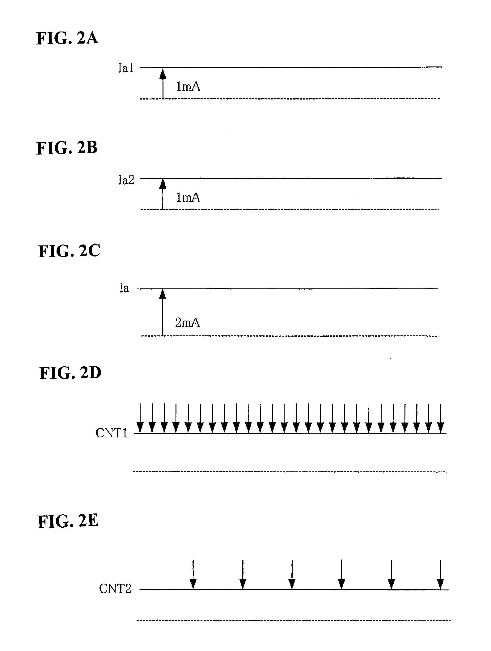
However, in this method, the power supply voltage Vcc will vary because while the A / D converting device 10 is in a constantly operating state, the A / D converting device 20 is in an intermittently operating state, producing a problem in that it is not possible to obtain stable A / D conversion values.
This makes it impossible to obtain a stable A / D conversion value CNT1.

Method used


Image

  • Measurement instrument
  • Measurement instrument
  • Measurement instrument

Examples


Embodiment Construction

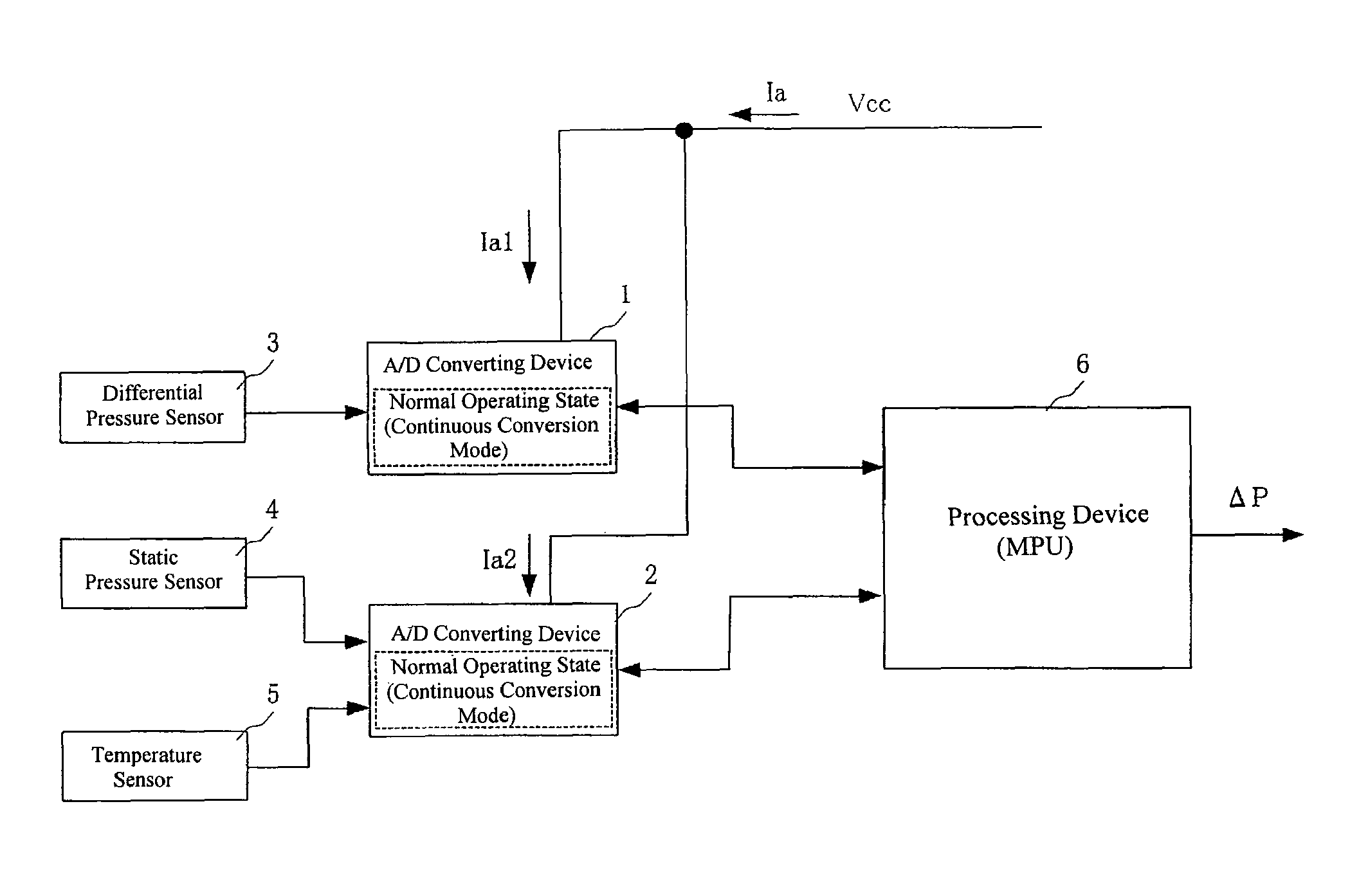
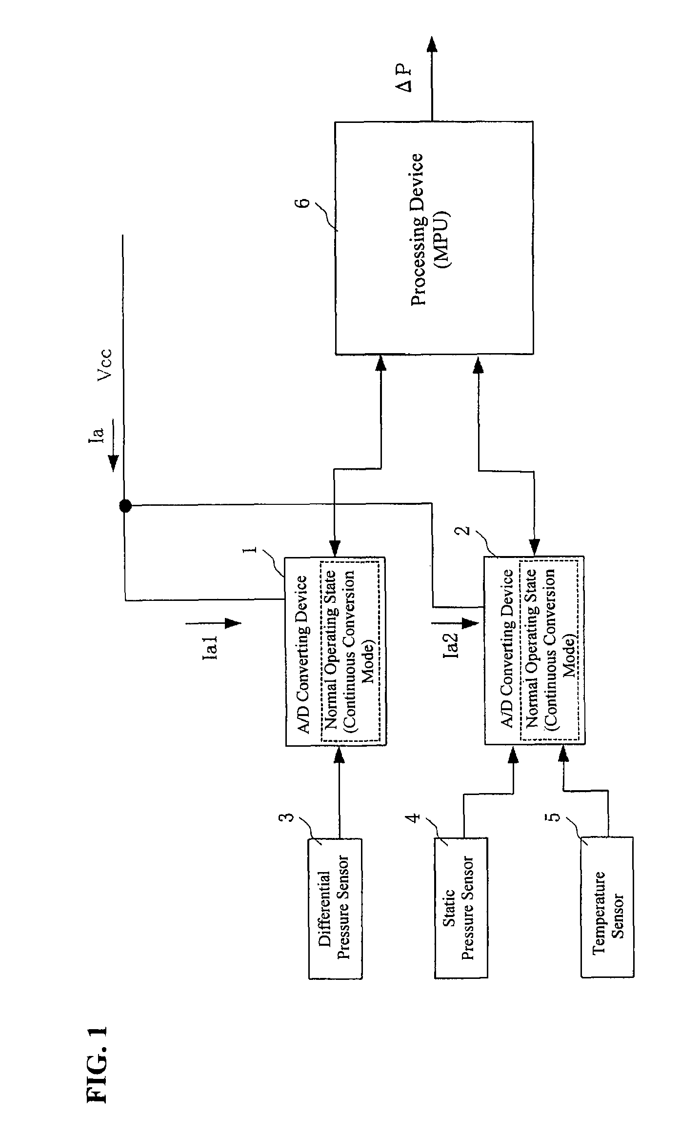
[0058]The present invention will be described in detail based on the drawings, below. FIG. 1 is a diagram illustrating the components in a differential pressure transmitting device that is one example of a measuring device according to the present invention. In the figure, 1 is a first A / D converting device, 2 is a second A / D converting device, 3 is a differential pressure sensor, 4 is a static pressure sensor, 5 is a temperature sensor, and 6 is a processing device, corresponding to the first A / D converting device 10, the second A / D converting device 20, the differential pressure sensor 30, the static pressure sensor 40, the temperature sensor 50, and the processing device 60 in the differential pressure transmitting device illustrated in FIG. 9.

[0059]In the differential pressure transmitting device illustrated in FIG. 9, the A / D converting device 10 is in a constantly operating state (a continuous converting mode), and the A / D converting device 20 is in an intermittently operating...


PUM


Abstract

One A / D converter and the other A / D converter have a common power supply voltage and sample an A / D conversion value at short time intervals and at a long time intervals, respectively. Both the A / D converter and the A / D converter are set in a constant active state (continuous conversion mode). This allows the total consumption current combining the consumption current of the A / D converter and the consumption current of the A / D converter to be constant, so that the power supply voltage is stabilized and a stable A / D conversion value can be obtained from each of the A / D converters.

Description

CROSS REFERENCE TO PRIOR APPLICATIONS[0001]This application is a U.S. National Phase application under 35 U.S.C. §371 of International Application No. PCT / JP2009 / 050368, filed on Jan. 14, 2009 and claims benefit of priority to Japanese Patent Application No. 2008-020723, filed on Jan. 31, 2008. The International Application was published in Japanese on Aug. 6, 2009 as WO 2009 / 096225 under PCT Article 21(2). All these applications are herein incorporated by reference.FIELD OF TECHNOLOGY[0002]The present invention relates to a measuring device, such as a differential pressure transmitting device.PRIOR ART[0003]Conventionally differential pressure transmitting devices have been used as devices for sensing and transmitting differential pressures of fluids. (See, for example, Japanese Unexamined Patent Application Publication H2-88921.) This differential pressure transmitting device comprises a differential pressure sensor, an A / D converting device, and a processing device, where a measu...

Claims


Application Information

Patent Timeline
Patent Type & Authority Patents(United States)
IPC IPC(8): G01L9/00G06F19/00G01L13/00G08C13/00
CPCG01L19/02G01L9/045
Inventor SHIMAKATA, TETSUYANOMIYAMA, TAKASHI
Owner YAMATAKE HONEYWELL CO LTD
Learn More