Perforating apparatus for tire constituent member

a technology of perforating apparatus and tire constituent, which is applied in the field of perforating apparatus for tire constituent members, can solve problems such as defective products

a technology of perforating apparatus and tire constituent, which is applied in the field of perforating apparatus for tire constituent members, can solve problems such as defective products

US20100024986A1Inactive Publication Date: 2010-02-04TOYO TIRE & RUBBER CO LTD

Image

  • Perforating apparatus for tire constituent member
  • Perforating apparatus for tire constituent member
  • Perforating apparatus for tire constituent member

Examples


Embodiment Construction

[0029]Subsequently, a mode for carrying out the invention will be described on the basis of an embodiment shown in the drawings.

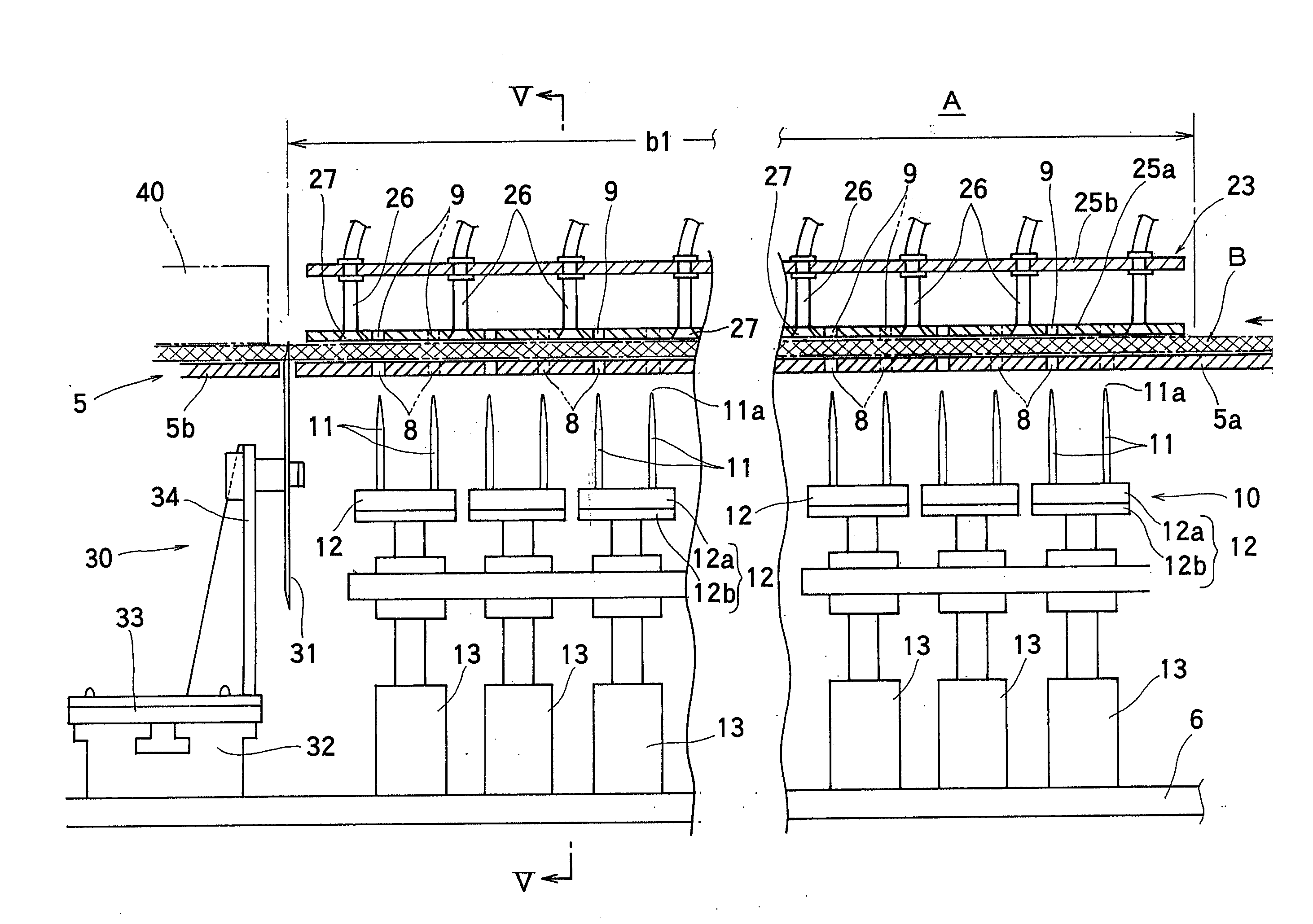
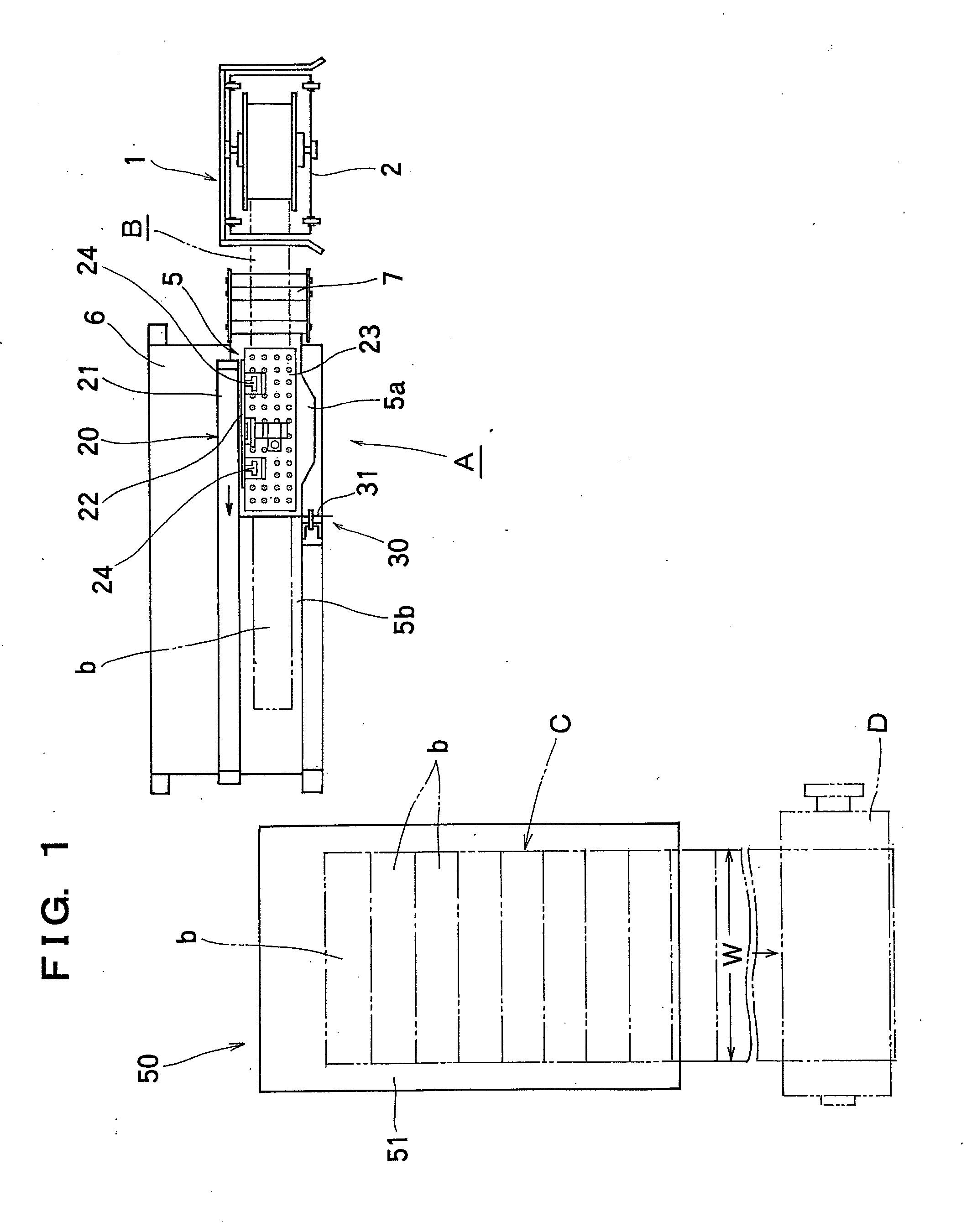
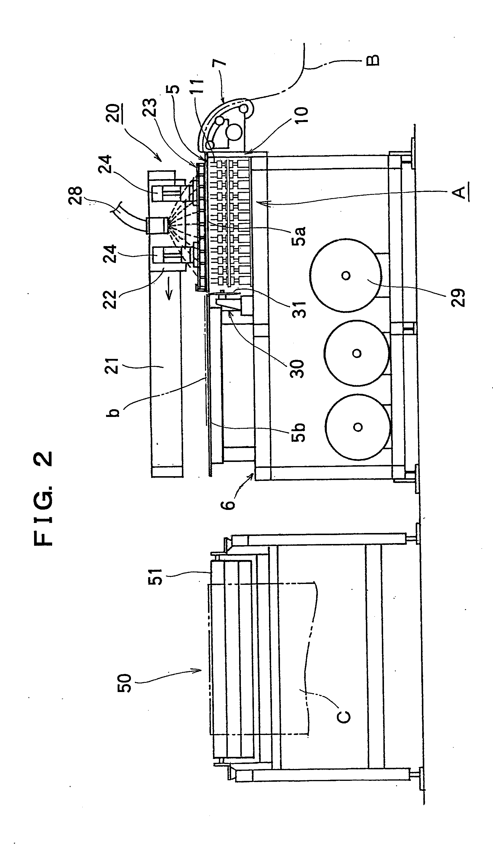
[0030]FIG. 1 is a schematic, plan view showing an outline of the whole of a perforating apparatus, according to the invention, for a tire constituent member, FIG. 2 is a schematic, front view showing the outline, and FIG. 3 is a side view showing the outline as viewed from a supply part side of a band-shaped material. An embodiment as shown shows a perforating apparatus constructed in combination with a cutting device, which cuts a band-shaped material to a predetermined length in the case where a tire constituent member is fabricated from the band-shaped material.

[0031]A carcass ply material C being a kind of a tire constituent member is obtained by cutting a band-shaped material B for ply to a length corresponding to a width W of the carcass ply material C on a building drum in a tire building process, truing up cut pieces b, which are cut in a manner of ...


PUM

PropertyMeasurementUnit
widthaaaaaaaaaa
widthaaaaaaaaaa
lengthaaaaaaaaaa

Abstract

The invention provides a perforating apparatus, which can efficiently form air vent holes in necessary locations on a tire constituent member and facilitates setting and changes of perforated positions to be able to readily accommodate for a change in size of the tire constituent member, and as perforating means 10, which performs a piercing action every one-time conveyance, a multiplicity of needle bodies 11 disposed on one of upper and lower sides of a feed table 5 of a band-shaped material B for the tire constituent member to be able to perpendicularly pierce the band-shaped material B on the feed table 5 are arranged in parallel in a direction of conveyance of and in a width direction of the band-shaped material B and provided to be controlled individually in respective sets, each set being composed of one or plural needle bodies 11, or each set being composed of one or plural rows of needles bodies in a width direction.

Description

TECHNICAL FIELD[0001]The present invention relates mainly to a perforating apparatus for a tire constituent member such as a carcass ply material, etc.BACKGROUND ART[0002]A carcass layer being one of tire constituent members of a pneumatic radial tire comprises a layer of a carcass ply material, in which reinforcement cords embedded in a rubber material and formed mainly from fiber are oriented in a radial direction of a tire, that is, a width direction, and a plurality of carcass ply materials having different widths are laminated.[0003]Such carcass ply material is fabricated by cutting a band-shaped material for ply, in which a multiplicity of the reinforcement cords are arranged in parallel to one another, covered with a rubber material, and embedded in the rubber material, to a length corresponding to a width of the carcass ply material, truing up ply material pieces, which are cut in a manner of a oblong strip, in a manner to make cut ends constituting both widthwise ends, and ...

Claims


Application Information

Patent Timeline
04 Feb 2010
Publication
US20100024986A1
IPC
B29D30/44
CPC
B26D1/18; B26D9/00; B29D30/0061; B26F1/24; B26F1/0084
Inventors
TATARA, TETSUO; TAKATSUKA, TOMOYUKI