Half bearing

a half bearing and bearing technology, applied in the direction of machines/engines, positive displacement liquid engines, mechanical equipment, etc., can solve the problems of large abrasion loss, difficult to form uneven shapes having a desired height, and inability to maintain the desired sliding ability for a long time, so as to prevent the sliding member from generating any adhesion, reduce the abrasion, and improve the effect of cavitation erosion resistan

Active Publication Date: 2015-11-12
SENJU METAL IND CO LTD
View PDF6 Cites 2 Cited by
  • Summary
  • Abstract
  • Description
  • Claims
  • Application Information

AI Technical Summary

Benefits of technology

[0013]In the half bearing according to the invention, by forming the uneven surface which maintains the oil to form an oil film and has a height that maintains the oil so that the oil film is formed against abrasion when a member to be slid is sliding, on a surface of the sliding layer slidably bearing the member to be slid, it is possible to form the oil reservoir on the surface of the sliding layer and to maintain the uneven shape on the surface of the sliding layer even under use conditions such that heavy load is applied.
[0014]This enables the oil film to be surely formed even under the boundary lubrication in which the heavy load is applied and it is difficult to form any oil film to decrease the abrasion. This also enables any heat generation to decrease so that it has excellent cavitation erosion resistance in an art of oil hydraulic machinery and thus, has an effect of preventing the sliding member from generating any adhesion.

Problems solved by technology

Such a sliding material in which a sliding layer is formed by the resin materials has excellent slidability but causes large abrasion loss, which is not suitable for usage under a heavy load condition.
However, under a heavy load condition like an oil hydraulic pump called a piston pump, there has been a case when it cannot maintain such uneven shapes so that it cannot maintain desired slidability in usage for a long time.
When increasing a height of the uneven shape, it is possible to avoid any disappearance of the oil reservoir by abrasion but it is difficult to form the uneven shape having a desired height on the surface of the sliding layer formed by the Cu series alloy.

Method used


Image

  • Half bearing
  • Half bearing
  • Half bearing

Examples


embodiments

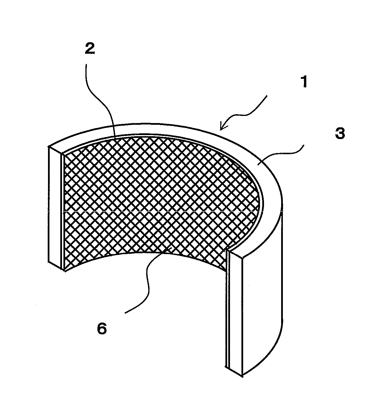
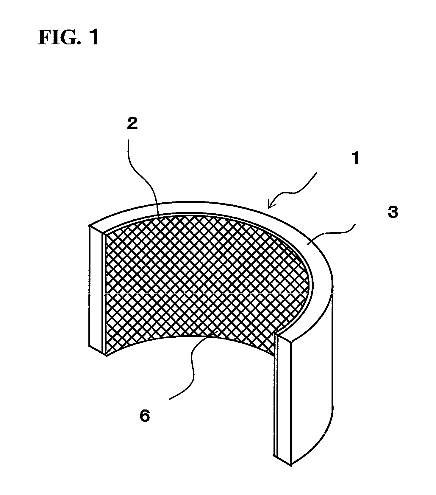
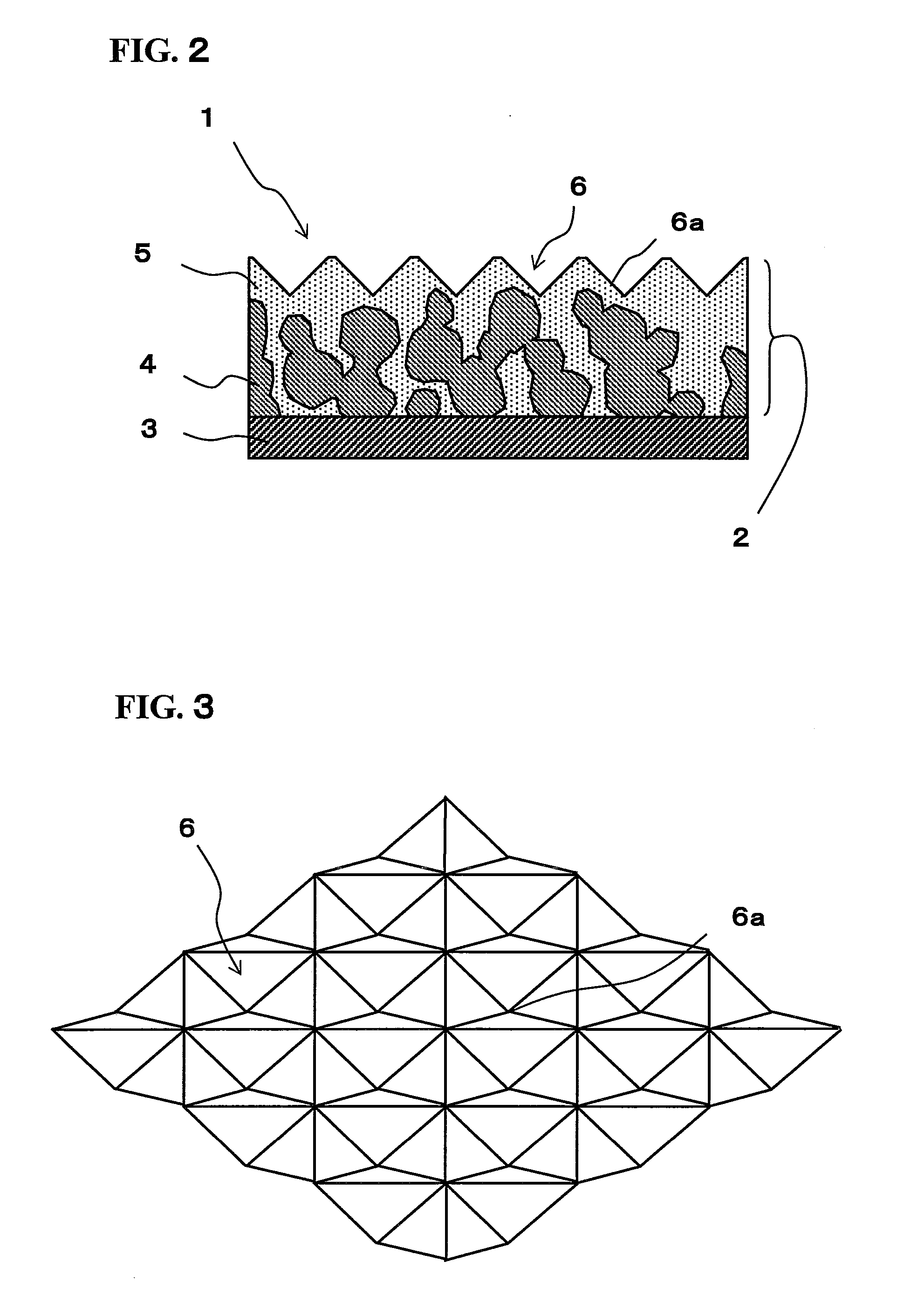
[0047]A test was carried out using the piston pump 10 shown in FIG. 4 in order to inspect any influence in which a difference in configuration of the sliding layer and a shape of the surface thereof in the half bearing was exerted to durability such as the adhesion and the abrasion. As the half bearing to be tested, they prepared the half bearing 1 as the embodiment in which the porous layer 4 composed of Cu—Sn series alloy was formed on the surface of the metal substrate 3, the resin material 5 including at least polytetrafluoroethylene and a carbon fiber coated the porous layer 4 to form the sliding layer 2, and the uneven surface 6 was formed on the surface of the sliding layer 2.

[0048]Further, they prepared the half bearing as the comparison example 1 in which the porous layer composed of Cu—Sn series alloy was formed on the surface of the metal substrate, and the resin material including polytetrafluoroethylene and lead (Pb) coated the porous layer to form a sliding layer 2. In...


PUM

PropertyMeasurementUnit
arithmetic average roughnessaaaaaaaaaa
particle sizeaaaaaaaaaa
arithmetic mean roughnessaaaaaaaaaa

Abstract

To provide a half bearing which has excellent abrasion resistance and surely forms an oil film under boundary lubrication in which it is difficult to form any oil film. A half bearing 1 formed on a circular arc along a direction in which the member to be slid swings is provided with a porous layer 4 composed of Cu—Sn series alloy, which is formed on a surface of a metal substrate 3, and a sliding layer 2 in which the porous layer 4 is covered with resin material 5 including at least polytetrafluoroethylene and a carbon fiber. An uneven surface 6 having a height which maintains oil to form an oil film and maintains the oil so that the oil film is formed against abrasion when a member to be slid is sliding, is formed on a surface of the sliding layer 2 slidably bearing the member to be slid.

Description

TECHNICAL FIELD[0001]The present invention relates to a half bearing which slidably bears a member to be slid.BACKGROUND OF THE INVENTION[0002]As the sliding member constituting a bearing, a sliding material has been known in which a porous layer composed of a copper (Cu) series alloy is formed on a metal substrate and resin materials mixing polytetrafluoroethylene (PTFE) and lead (Pb) coats this porous layer.[0003]Such a sliding material in which a sliding layer is formed by the resin materials has excellent slidability but causes large abrasion loss, which is not suitable for usage under a heavy load condition. Since the usage of Pb is being limited, any sliding material free from Pb has been developed.[0004]As the sliding member constituting a bearing, a sliding material in which Cu series alloy is stuck to a metal substrate has been also known. The sliding material in which Cu series alloy is stuck to the metal substrate such as copper plated steel plate and the like has less sl...

Claims


Application Information

Patent Timeline
Patent Type & Authority Applications(United States)
IPC IPC(8): F16C33/20F16C33/04
CPCF16C33/206F16C33/201F16C33/046F16C33/103F04B27/086F05C2253/12F05C2253/20F16C2300/28F16C2360/44F16C2220/20F16C2208/02F16C2240/54F16C2208/32B22F7/06
Inventor SATO, NAOKIKURATA, RYOICHI
Owner SENJU METAL IND CO LTD
Why Eureka
Try Eureka