Construction machine

Active Publication Date: 2010-02-04
HITACHI CONSTR MASCH CO LTD
View PDF16 Cites 25 Cited by
  • Summary
  • Abstract
  • Description
  • Claims
  • Application Information

AI Technical Summary

Benefits of technology

[0029]In this case, right and left side weight portions of a smaller height are provided on the both opposite sides of a center weight portion of a larger height, so that it becomes possible to increase the heaviness of the counterweight by way of the two side weight portions. T

Problems solved by technology

Therefore, an upper revolving structure does not have an ample space for onboard equipments.
That is to say, a lot of onboard equipments are necessarily confined to a narrow space.
However, in the case of a small size hydraulic excavator, it is difficult to secure a sufficient space around the air cleaner for mounting and dismantling a filter element.
By the way, in the invention of Patent Literature 1 just mentioned, considerable time and efforts are required for l

Method used


Image

  • Construction machine
  • Construction machine
  • Construction machine

Examples


Embodiment Construction

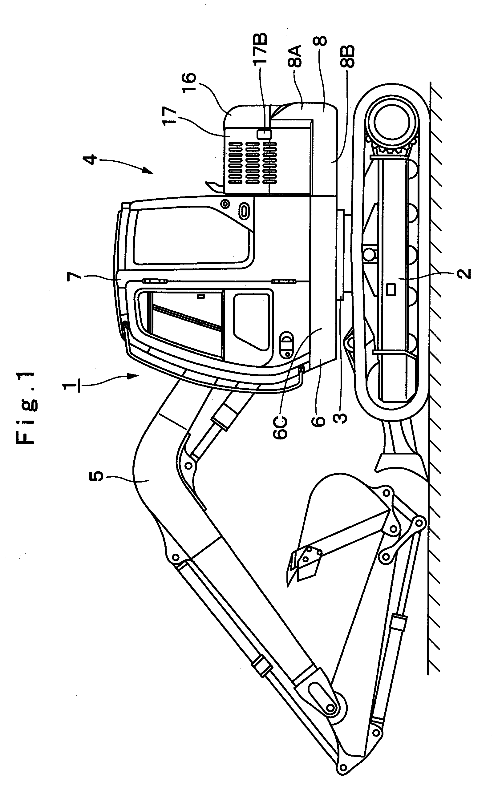
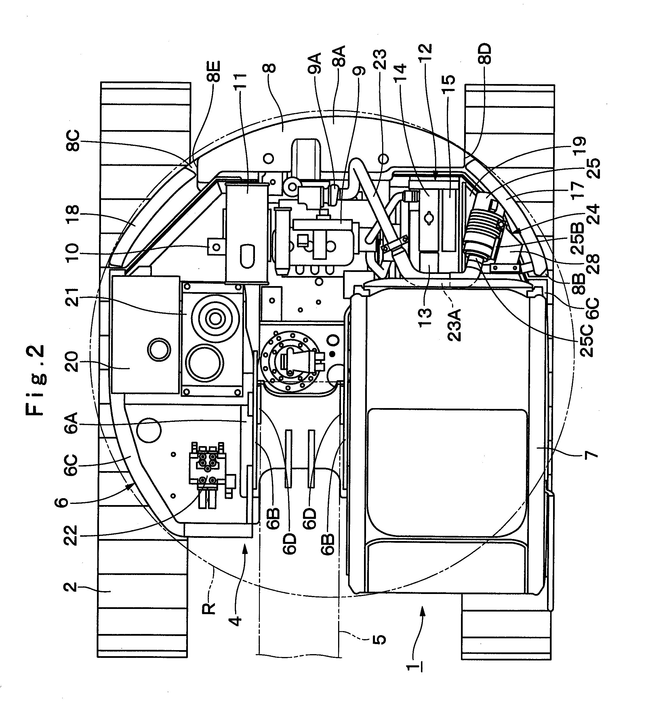
[0071]Hereafter, with reference to FIGS. 1 through 7 of the accompanying drawings, a detailed description will be given of an ultra-mini rear revolving type hydraulic excavator, taken as a typical example of construction machines in accordance with an embodiment of the present invention.

[0072]In FIG. 1, indicated at 1 is a hydraulic excavator as an example of construction machines. The hydraulic excavator 1 is built in a form which generally called ultra-mini rear revolving type hydraulic excavator having an upper revolving structure 4 which can be put in swing motions within a range substantially corresponding to a transverse width of a vehicle body of a vehicular lower structure 2, which will be described hereinafter. The hydraulic excavator 1 is largely constituted by an automotive crawler type vehicular lower structure 2, an upper revolving structure 4 which is swingably mounted on the vehicular lower structure 2 through a revolving ring 3, and a working mechanism 5 liftably mou...


PUM


Abstract

A counterweight (8) is attached to the rear side of a revolving frame (6), and an engine (9) is mounted in a transverse direction in front of the counterweight (8). A heat exchanger (12) is located on the left side of the engine (9), and a left-hand side door (17) is located on the left side of the heat exchanger (12). An air cleaner (24) is accommodated in an air cleaner chamber (19) which is provided in a space enclosed by the counterweight, left-hand side door and heat exchanger. In this state, a casing (25) of the air cleaner has an opening portion (25A) to permit insertion and extraction of a filter element (26). Thus, at the time of a maintenance work for the air cleaner, one can draw out the filter element from the opening portion of the casing simply by opening the left-hand side door.

Description

TECHNICAL FIELD[0001]This invention relates to construction machines such as hydraulic excavators and hydraulic cranes, and more particularly to a construction machine, which is provided with an air cleaner for cleaning engine intake air.BACKGROUND ART[0002]Generally, a construction machine like a hydraulic excavator which is built of a vehicular lower structure, an upper revolving structure swingably mounted on the vehicular lower structure, and a working mechanism liftably mounted at the front of the upper revolving structure and a ground excavating operation is performed by lifting up and down the working mechanism.[0003]The upper revolving structure is largely constituted by a revolving frame having the working mechanism mounted at a front side, a cab which is mounted in a left front side of the revolving frame and an operator gets on board, a counterweight which is provided at the rear portion of the revolving frame as a weight balance relative to the working mechanism, an engi...

Claims


Application Information

Patent Timeline
IPC IPC(8): B60K13/02B62D33/06
CPCB62D49/085E02F9/18E02F9/0891E02F9/08F02M35/04F02M35/02E02F9/00
Inventor MATSUSHITA, MAKOTONAKAMURA, MASAOTAMURA, KAZUHISA
Owner HITACHI CONSTR MASCH CO LTD
Why Eureka
Try Eureka