

Energy storage mechanism for switching device
- Summary
- Abstract
- Description
- Claims
- Application Information
AI Technical Summary
Benefits of technology
Problems solved by technology
Method used
Image

Examples
embodiment 1
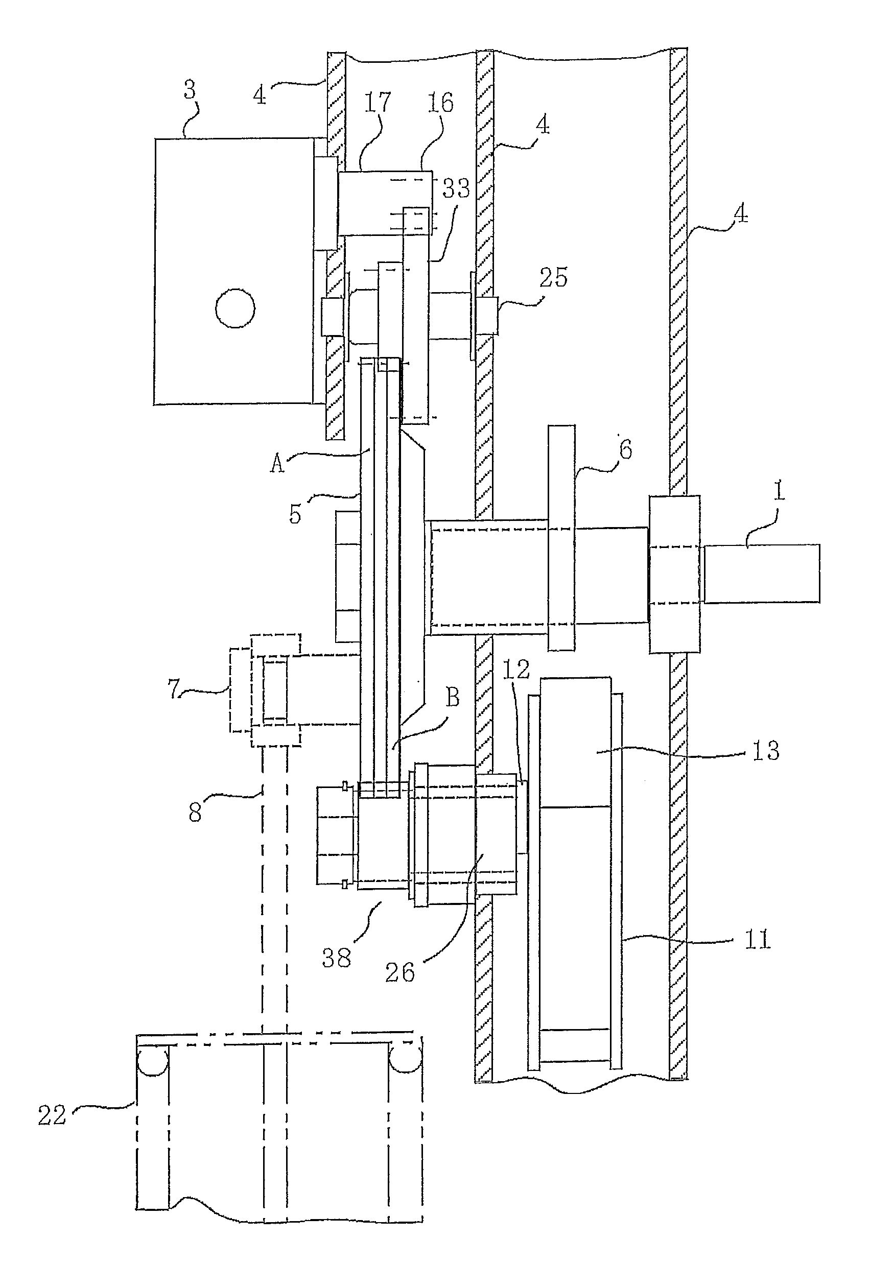
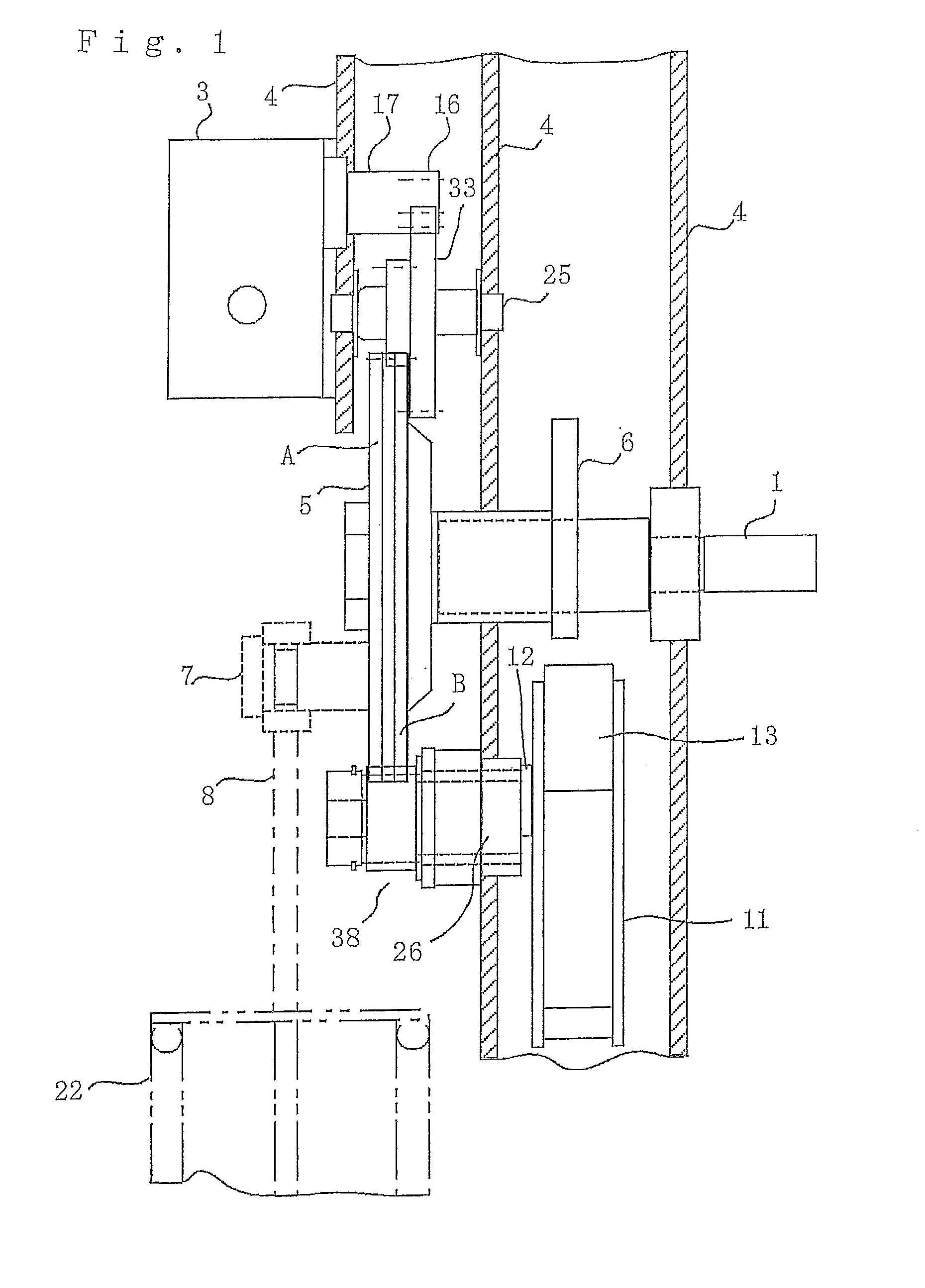
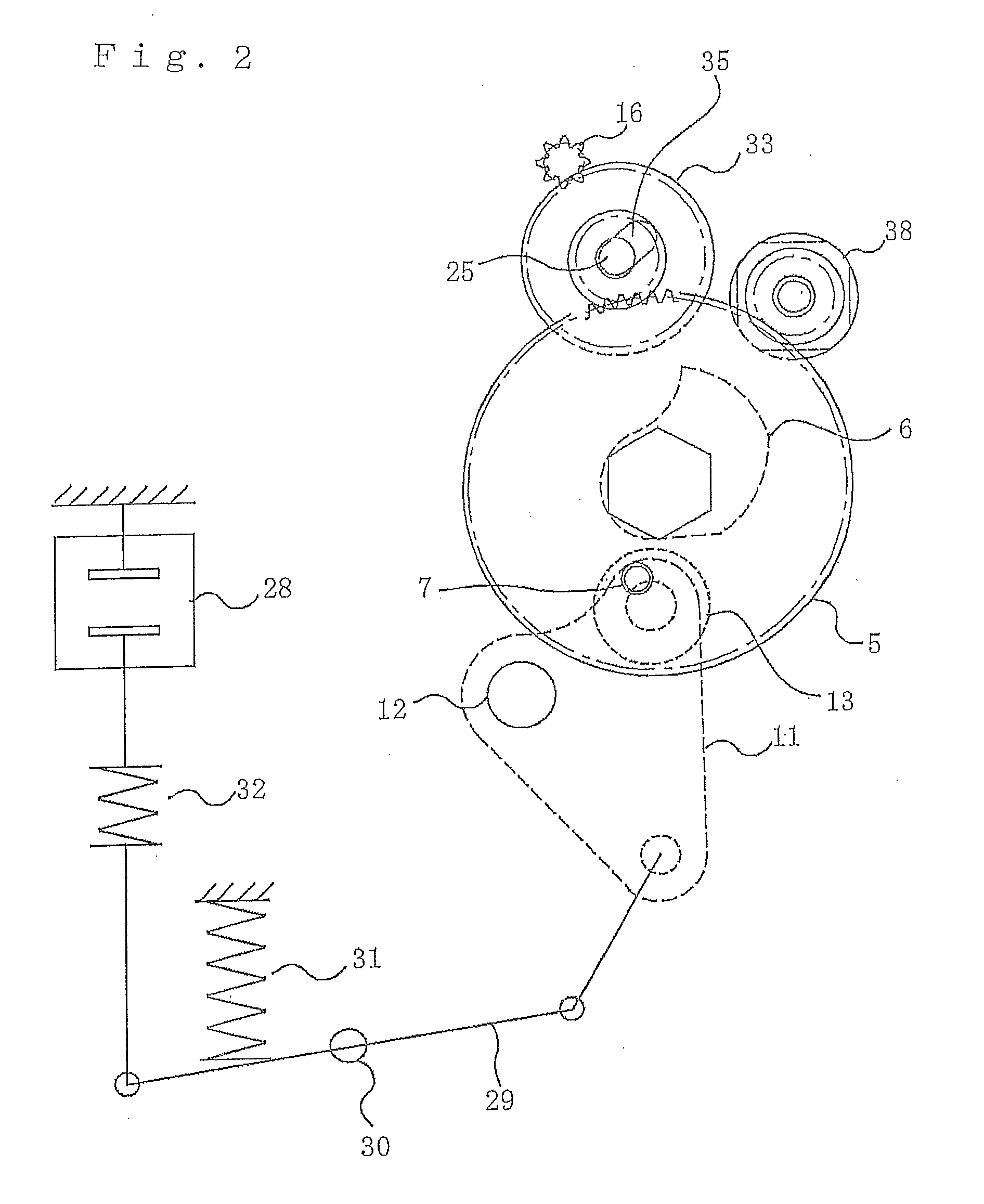
[0030]FIG. 1 is a side cross-sectional view illustrating principal parts of an energy storage mechanism, for a switching device, according to Embodiment 1 of the present invention. FIG. 2 is a diagram for explaining the main configuration of the energy storage mechanism for a switching device as well as for explaining a state in which a closing spring has been energized. The same reference marks in the figures indicate the same or equivalent constituent elements. The energy storage mechanism is provided with a main shaft 1, a rotation axle 25, an output shaft 17, and a shaft 26 of a reverse rotation prevention gear that are commonly supported by a supporting frame 4 in such a way as to be approximately parallel to one another. The main shaft 1 holds in a fitting manner a main gear (large gear) 5 at the protrusion end thereof protruding from one side of the supporting frame 4 and a closing cam 6 at the middle portion thereof; the main gear 5 and the closing cam 6 rotate on the main s...
PUM
 Abstract
Description
Claims
Application Information