Structure of transformer

a transformer and structure technology, applied in the direction of transformer/inductance details, coils, electrical equipment, etc., can solve the problems of increased transformer fabrication cost, insufficient throughput, and electrical interference, and achieve the effect of simple and easy assembly

Inactive Publication Date: 2010-02-04
DELTA ELECTRONICS INC
View PDF13 Cites 20 Cited by
  • Summary
  • Abstract
  • Description
  • Claims
  • Application Information

AI Technical Summary

Benefits of technology

[0005]It is an object of the present invention to provide a transformer having a simple and easily assembled structure.

Problems solved by technology

For example, during power conversion of the transformer 1, the magnetic core assembly 11 is readily charged and thus suffered from electromagnetic interference (EMI).
The arrangement of the copper foil may increase the fabricating cost of the transformer.
Furthermore, the procedure of winding the copper foil around the outer periphery of the transformer 1 is very labor-intensive and time-consuming and thus the throughput is insufficient.

Method used


Image

  • Structure of transformer
  • Structure of transformer
  • Structure of transformer

Examples


Embodiment Construction

[0015]The present invention will now be described more specifically with reference to the following embodiments. It is to be noted that the following descriptions of preferred embodiments of this invention are presented herein for purpose of illustration and description only. It is not intended to be exhaustive or to be limited to the precise form disclosed.

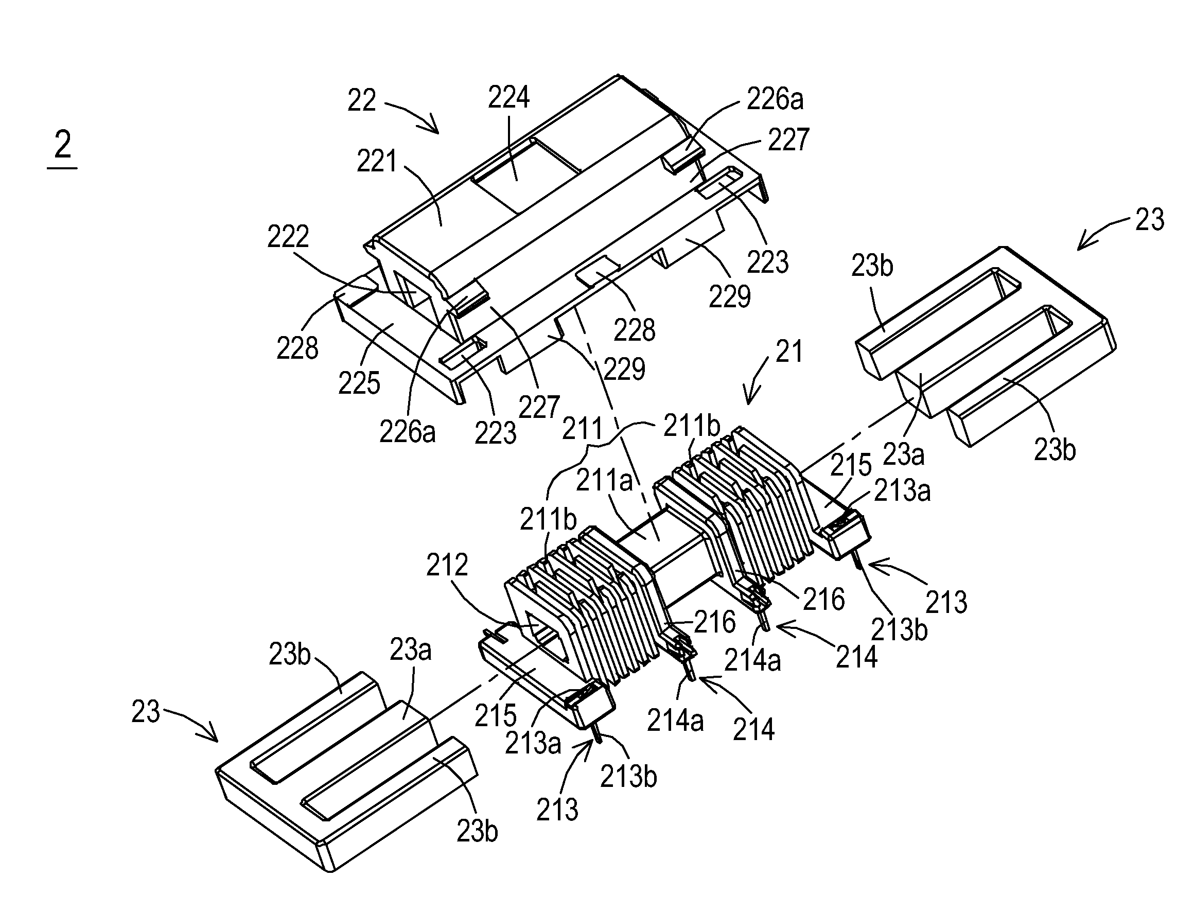
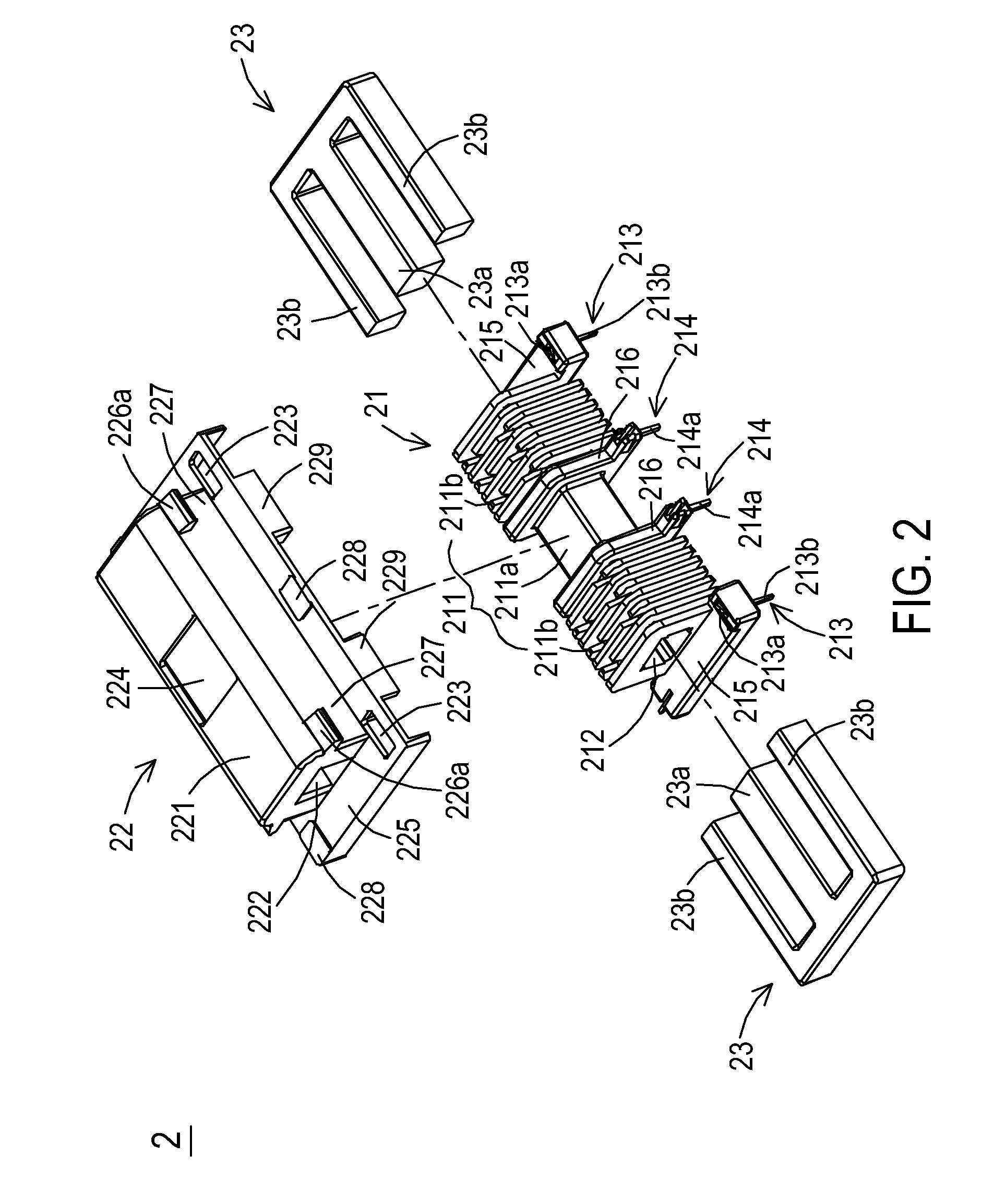
[0016]FIG. 2 is a schematic exploded view of a transformer according to a preferred embodiment of the present invention. The transformer 2 principally comprises a bobbin 21, a case 22 and a magnetic core assembly 23. An example of the magnetic core assembly 23 includes but is not limited to an EE-type core assembly, which are composed of two E-shaped magnetic parts. Each E-shaped magnetic part includes a middle portion 23a and two leg portions 23b, which are disposed at bilateral sides of the middle portion 23a.

[0017]The bobbin 21 comprises a winding member 211, a channel 212, multiple ground pins 213, multiple conductive pins 2...


PUM

PropertyMeasurementUnit
included angleaaaaaaaaaa
conductiveaaaaaaaaaa
lengthaaaaaaaaaa

Abstract

A transformer includes a bobbin, a primary winding coil, a secondary winding coil, a case and a magnetic core assembly. The bobbin includes a winding member, a first channel, and multiple ground pins. The ground pins have first terminal parts protruded from a surface of the winding member. The primary winding coil and the secondary winding coil wound around the winding member. The case includes a receiving portion for partially accommodating the winding member therein, a second channel communicated with the receiving portion, and multiple perforations corresponding to the ground pins. The first terminal parts are penetrated through the perforations and protruded from a surface of the case when the winding member is accommodated in the receiving portion. The magnetic core assembly is partially embedded into the first channel and the second channel, so that the magnetic core assembly is contacted with the first terminal parts of the ground pins.

Description

FIELD OF THE INVENTION[0001]The present invention relates to a transformer, and more particularly to a transformer having a simple and easily assembled structure and low electromagnetic interference.BACKGROUND OF THE INVENTION[0002]A transformer has become an essential electronic component for voltage regulation into required voltages for various kinds of electric appliances. Referring to FIG. 1, a schematic exploded view of a conventional transformer is illustrated. The transformer 1 principally comprises a magnetic core assembly 11, a bobbin 12, a primary winding coil 13, a secondary winding coil 14 and an insulating tape 15. The bobbin 12 comprises a first side plate 121, a second side plate 122 and a winding member 123. The insulating tape 15 is wound around the middle portion of the winding member 123. The winding member 123 is divided into a first winding section 1231 and a second winding section 1232, which are located at bilateral sides of the insulating tape 15. The primary...

Claims


Application Information

Patent Timeline
Patent Type & Authority Applications(United States)
IPC IPC(8): H01F27/34
CPCH01F27/266H01F2027/297H01F2005/043H01F27/325
Inventor LIN, TSAI-SHENGZHANG, ZHI-LIANGCHUNG, HIS-KUOLIAO, CHUN-HAO
Owner DELTA ELECTRONICS INC
Why Eureka
Try Eureka