Near-field radio frequency identification reader antenna

a reader antenna and radio frequency identification technology, applied in the direction of resonant antennas, particular array feeding systems, stripline fed arrays, etc., can solve the problems of deterioration of the use efficiency of the reader antenna port, the size and price of the tag, and the inability to recognize the tag

Inactive Publication Date: 2010-02-04
ELECTRONICS & TELECOMM RES INST
View PDF12 Cites 24 Cited by
  • Summary
  • Abstract
  • Description
  • Claims
  • Application Information

AI Technical Summary

Benefits of technology

[0013]An aspect of the present invention provides a near-field radio frequency identification (RFID) reader antenna that can form a plurality of pairs of slots on a ground surface of a single dielectric l

Problems solved by technology

Generally, for the item level tagging, RFID technology of a high frequency (HF) band has been preferred but has currently caused a number of problems including the size and price of the tag, recognition distance, a data processing speed, compatibility with an existing RFID standard of an ultra high frequency (UHF) band, and the like.
However, when u

Method used


Image

  • Near-field radio frequency identification reader antenna
  • Near-field radio frequency identification reader antenna
  • Near-field radio frequency identification reader antenna

Examples


Embodiment Construction

[0028]Reference will now be made in detail to exemplary embodiments of the present invention, examples of which are illustrated in the accompanying drawings, wherein like reference numerals refer to the like elements throughout. The exemplary embodiments are described below in order to explain the present invention by referring to the figures.

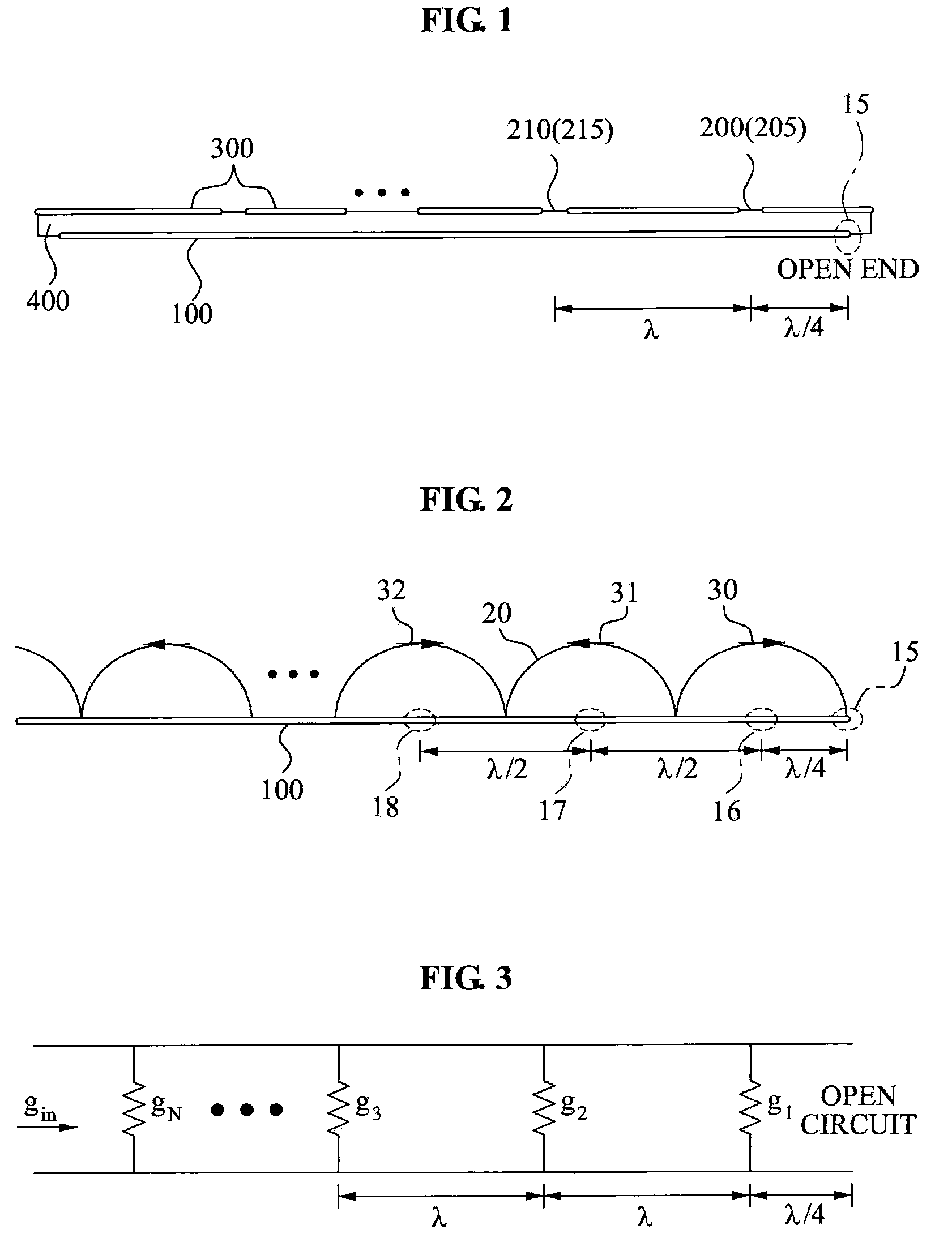
[0029]FIG. 1 is a side cross-sectional view illustrating a near-field radio frequency identification (RFID) reader antenna according to an embodiment of the present invention.

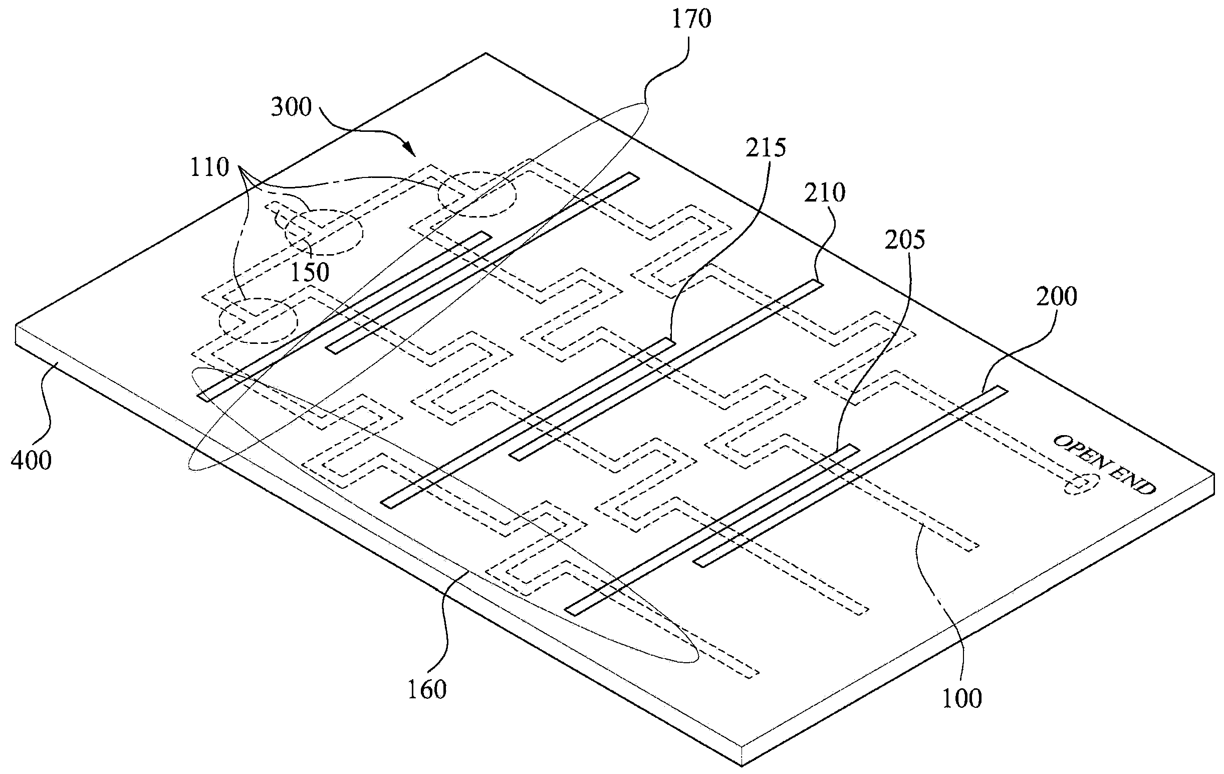
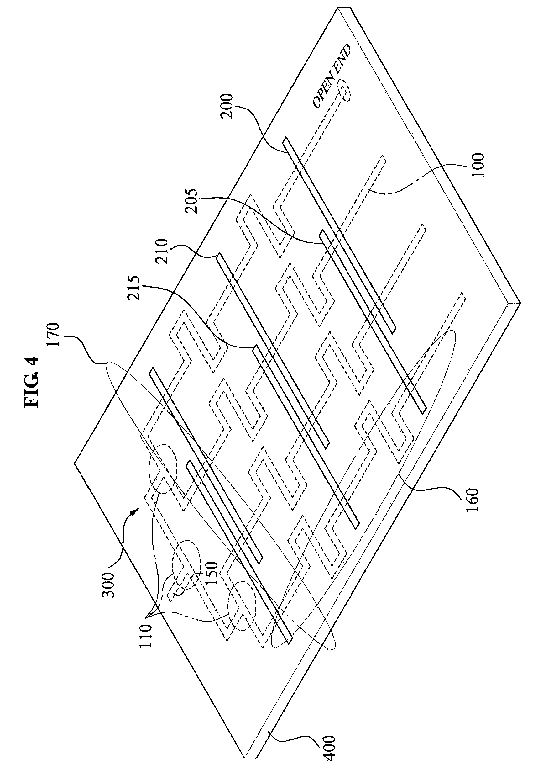
[0030]The near-field RFID reader antenna forms a plurality of pairs of slots 200 and 205, and 210 and 215 on a ground surface 300 of a single dielectric layer 400 or a single dielectric substrate to emit a field, and forms a micro-strip line 100 with an open end 15 on another surface of the single dielectric layer 400 to feed the plurality of pairs of slots 200 and 205, and 210 and 215.

[0031]As shown in FIG. 1, the ground surface 300 includes a first pair of slots 200 and ...


PUM


Abstract

A near-field radio frequency identification (RFID) reader antenna includes: a plurality of pairs of slots being formed on a ground surface of a single dielectric layer to emit a field; and a micro-strip line being formed on another surface of the single dielectric layer and having an open end to feed the plurality of pairs of slots.

Description

CROSS-REFERENCE TO RELATED APPLICATION[0001]This application claims priority from Korean Patent Application No. 10-2008-0076036, filed on Aug. 4, 2008, in the Korean Intellectual Property Office, the entire disclosure of which is incorporated herein by reference.BACKGROUND OF THE INVENTION[0002]1. Field of the Invention[0003]The present invention relates to a near-field radio frequency identification (RFID) reader antenna that can form a plurality of pairs of slots on a ground surface of a single dielectric layer to emit a field and form a micro-strip line with an open end on another surface of the single dielectric field to feed the plurality of pairs of slots and thereby uniformly form the magnitude and phase of an electric field on the plurality of pairs of slots, and also can readily recognize a large number of tags approaching the near-field RFID reader antenna.[0004]This work was supported by the IT R&D program of MIC / IITA. [2008-F-052-01, Near-Field RFID Reader Antenna for It...

Claims


Application Information

Patent Timeline
IPC IPC(8): H01Q1/38
CPCH01Q1/2216H01Q21/068H01Q21/0081H01Q13/22H01Q1/38
Inventor CHOI, WON KYUKIM, JEONGSEOKBAE, JI-HOONCHOI, GIL YOUNGCHAE, JONG-SUK
Owner ELECTRONICS & TELECOMM RES INST
Why Eureka
Try Eureka