Ink Jet Recording Device

a recording device and ink jet technology, applied in printing and other directions, can solve the problems of inability to control the concentration of ink within the desired concentration range, the ink once entering the gutter may backflow and overflow, and the suction force of ink may reduce, so as to achieve stable printing quality, reduce the solvent discharge amount of the recording device, and be stable. operable

Active Publication Date: 2010-02-04
HITACHI IND EQUIP SYST CO LTD
View PDF46 Cites 3 Cited by
  • Summary
  • Abstract
  • Description
  • Claims
  • Application Information

AI Technical Summary

Benefits of technology

[0018]According to the present invention, an amount of solvent discharged from the ink jet recording device can be reduced by arbitrarily controlling the circulation of exhaust gas and the discharging of the exhaust gas outside the device, and printing with stable quality can be obtained.
[0019]Moreover, according to the present invention, a stably operable ink jet recording device can be provided in which the ink once entered the gutters is prevented from back-flowing by connecting an exhaust path block between an ink inflow port of an ink flow path block and an ink collision plane, splashes during collision of the ink particles are eliminated by causing the exhaust flow path block to be a circular pipe, and the solvent vapor is prevented from flown out and air intake from external air is prevented by employing such a structure in which the concave part and the convex part of a connection portion of the ink flow path block and the exhaust flow path block closely fit with each other, or perfectly blocking the connection portion.
[0020]Moreover, according to the present invention, solvent vapor returned to the ink container at the same time when the ink is recovered from the gutters, can be efficiently circulated inside the ink jet recording device, thereby, it is not necessary to discharge the solvent matter content outside the device. Moreover, an ink jet recording device which has two or more jet nozzles and which can recover collected ink to the ink container without overflowing.

Problems solved by technology

On the other hand, if the technology of circulating the exhaust gas is continuously used, volatilized amount of solvent components from the ink becomes small since circulating exhaust gas is saturated with solvent vapor, so that there is a problem that control of the ink concentration within a desired concentration range will be difficult, disabling a stable and good printing result to be obtained.
For this reason, although the gutter has a function to receive ink particles not used for printing, and by sucking them using negative pressure to recover them into an ink container, there has been a problem that, at some connection positions between the ink flow path of the gutter and the solvent vapor exhausted from the ink container, the suction force for the ink may reduce, and the ink once entered the gutter may back-flow and overflow, resulting in pollution of environment of the device.
Moreover, there has also been a problem that if the ink collides vertically to an ink collision plane in the gutter, scattered ink droplets occur during collision, and in some cases, they may fly out from the gutter and collide with ink particles for printing, resulting in disturbance of printing.
Further, there has also been a problem that if the connection between a path connected to the ink container and the gutter is imperfect, the solvent vapor is flown out from the imperfection part, and air is taken in from external air.
However, a technology to provide a flow path for supplying gas taken in during recovering ink into the gutter with the device having two jet nozzles has not been proposed.
This leads to collapse of the balance between the recovery amount and the supply amount of the gas, thereby, disables the gutter A to circulate at 100%, causing a part of the solvent vapor supplied to the gutter A to be discharged outside the device from the collection port of gutter A. Moreover, if the gas circulates only through the gutter A, there is possibility that the gutter B to which the gas is not supplied cannot take in gas, and due to poor suction force for ink, the ink collected by the gutter B overflows from the collection port of the gutter.

Method used


Image

  • Ink Jet Recording Device
  • Ink Jet Recording Device
  • Ink Jet Recording Device

Examples


first embodiment

[0038]Hereinafter, a first embodiment will be described.

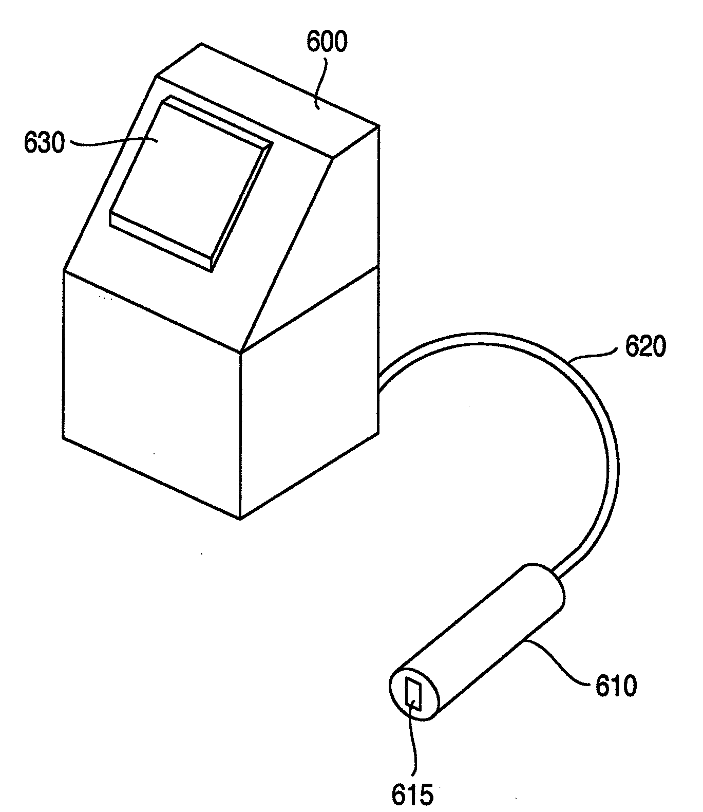
[0039]FIG. 3 is shows the configuration of an ink jet recording device according to a first embodiment of the present invention. The ink jet recording device comprises a main body 600 which contains a control system and a circulation system, a printing head 610 having a nozzle which jets ink to generate ink particles, and a cable 620 connecting the main body 600 and a circulation system and a control system in the printing head 610.

[0040]The main body 600 is equipped with a liquid crystal panel 630 enabling a user to input print content, print specification and the like, and content of control, an operation state of the device, and the like to be displayed, and an operation control part of the control system.

[0041]The printing head 610 is covered with a cover made of stainless steel, in which a printing part to generate ink particles and to control flight of the ink particles is contained. A hole 615 provided in the bottom surf...

second embodiment

[0066]Hereinafter, a second embodiment will be described with reference to drawings. Note that descriptions with regard to parts which are common to the above-mentioned first embodiment will be eliminated.

[0067]FIG. 7 is a view illustrating a prior art technology mode in which exhaust gas is supplied to a printing head 32. The ink jet recording device is separated into a main body 31 and a printing head 32, and between them are connected by a cable for protecting a piping tube and an electric wire. The ink in the ink container 33 in the main body 31 is sucked by the supply pump 34, and then fed to a secondary side.

[0068]Foreign mattes in the pumped ink are removed by a filter 35, and then adjusted to a predetermined pressure by a pressure regulator 36. Wile the adjusted pressure being monitored by a pressure gauge 37, the ink is sent to the printing head 32. The ink is made ink particles 39 by jetted from a nozzle 38, and electrified by an electrification electrode 40 according to n...

third embodiment

[0081]Hereinafter, a third embodiment will be described with reference to drawings. Note that descriptions with regard to parts which are common to those in the above mentioned embodiments are eliminated.

[0082]The configuration of the third embodiment illustrated in FIG. 10 uses a manual type valve 55 instead of the 3-port electromagnetic valve 49 in the second embodiment. In operation of the manual type valve 55, by causing the exhaustion path 48 and the exhaust circulation path 50 to be in open state, the discharge outside device path 51 can be closed, and on the other hand, by causing the exhaustion path 48 and the exhaust circulation path 50 to be in closed state, the discharge outside device path 51 can be open state. This configuration enables an operator of the ink jet recording device to arbitrarily switch between the exhaust circulation and the discharge outside device.

[0083]FIG. 11 shows the operational flow of the ink jet recording device according to the present embodime...


PUM


Abstract

An ink jet recording device comprises a main body equipped with an ink container, an ink supply pump ink, an ink recovery pump, and a control unit. A printing head equipped with a nozzle emits ink supplied from the main body as ink particles. An electrification electrode electrifies the ink particles and a deflection electrode deflects the electrified ink particles. A gutter collects ink particles which are not used for printing. An exhaust circulation path connects the ink container and the gutter. The gutter comprises two members of an ink flow path block in which ink flows and an exhaust flow path block in which exhaust solvent vapor flows.

Description

CROSS-REFERENCE TO RELATED APPLICATION(S)[0001]This is a divisional application of U.S. patent application Ser. No. 12 / 074,171, filed Feb. 28, 2008, which application claims priority from Japanese Application 2008-015748 filed on Jan. 28, 2008, the entire disclosure of which is incorporated herein by reference.BACKGROUND OF THE INVENTION[0002]The present invention relates to an ink jet recording device for, using jetted ink particles, printing letters or characters or drawing patterns on an object to be printed, which is conveyed in a production line.[0003]According to such an ink jet recording technology, it is possible to reduce volatilization of solvent components from the ink by supplying exhaust gas to a printing head and circulating the same. However, in an ink jet recording device, since solvents used during nozzle washing when operation of the device is stopped and the other maintenances enter an ink circulation path, ink concentration will be reduced.[0004]For this reason, ...

Claims


Application Information

Patent Timeline
Patent Type & Authority Applications(United States)
IPC IPC(8): B41J2/165
CPCB41J2/18B41J2/03
Inventor NAGAMINE, TOSHIHIDEMIYAO, AKIRAFUJIKURA, SEIJIMATSUDA, TADAYUKIKOTABE, HIROSHIINOUE, TOMOHIRO
Owner HITACHI IND EQUIP SYST CO LTD
Why Eureka
Try Eureka