
Electro-optic unit, driving method of the electro-optic unit, and display apparatus having the same

Active Publication Date: 2010-02-04
SAMSUNG DISPLAY CO LTD
View PDF9 Cites 145 Cited by
  • Summary
  • Abstract
  • Description
  • Claims
  • Application Information

AI Technical Summary

Benefits of technology

[0012]The present invention also provides an electro-optic unit and a display device having the same that may quickly achieve a 2D / 3D conversion, and manufacturing of an enlarged display device that may be easily achieved.

Problems solved by technology

However, the anisotropic lens may be expensive and the manufacturing process may be complex, and the refractive-index anisotropy of liquid crystal or polymer liquid crystal may be smaller than a required refractive-index anisotropy, and thus manufacturing a large-size panel may be difficult.
For example, in the case of a 52-inch 9-view 3D display, a 100 μm cell gap or lens thickness may be required, but alignment of a 100 μm thick liquid crystal layer may be very difficult.

Method used


Image

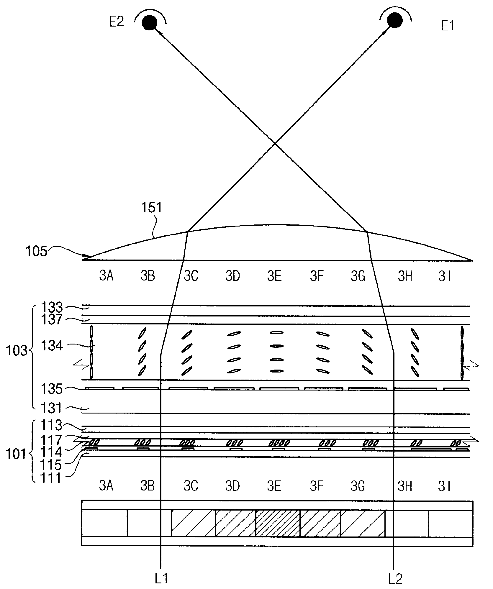
  • Electro-optic unit, driving method of the electro-optic unit, and display apparatus having the same
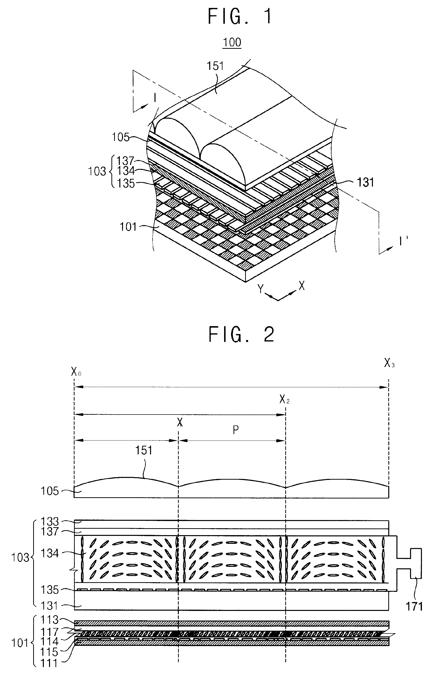
  • Electro-optic unit, driving method of the electro-optic unit, and display apparatus having the same
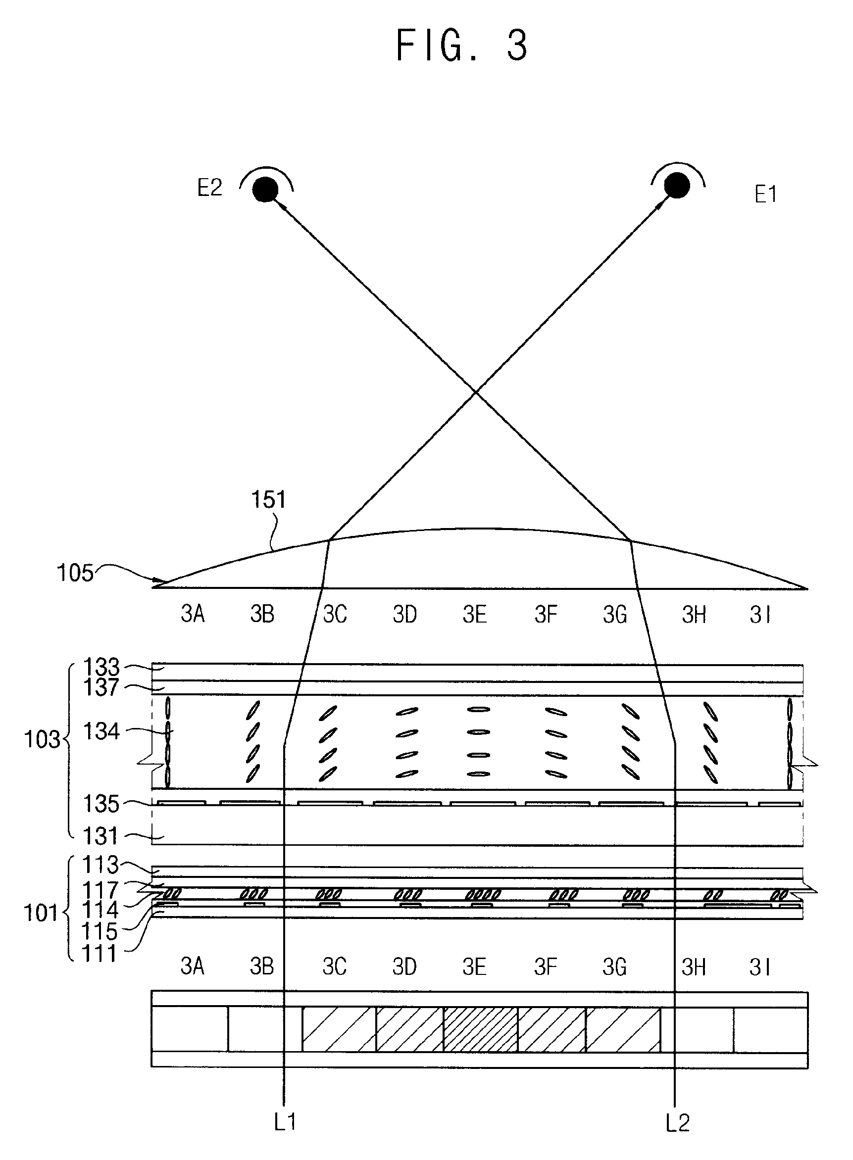
  • Electro-optic unit, driving method of the electro-optic unit, and display apparatus having the same

Examples


Embodiment Construction

[0057]The invention is described more fully hereinafter with reference to the accompanying drawings, in which exemplary embodiments of the invention are shown. This invention may, however, be embodied in many different forms and should not be construed as limited to the exemplary embodiments set forth herein. Rather, these exemplary embodiments are provided so that this disclosure is thorough, and will fully convey the scope of the invention to those skilled in the art. In the drawings, the size and relative sizes of layers and regions may be exaggerated for clarity. Like reference numerals in the drawings denote like elements.

[0058]It will be understood that when an element or layer is referred to as being “on,”“connected to” or “coupled to” another element or layer, it can be directly on, connected or coupled to the other element or layer or intervening elements or layers may be present. In contrast, when an element is referred to as being “directly on,”“directly connected to” or ...


PUM


Abstract

The present invention provides an electro-optic unit. A lens unit disposed at an upper portion of a display panel has a plurality of lens part. An electro-optic unit is disposed between a display panel and a lens unit, and includes an electro-optic material layer formed as a graded refractive index lens in an electric field. A display device shows a two-dimensional and a three-dimensional image according to a mode of the electro-optic unit. A driving part may form the graded refractive index lens to have the same pitch as the pitch of the lens part. The graded refractive index lens may be formed as a convex lens or a Fresnel lens. The electro-optic unit is displayed to form the Fresnel lens. A driving method enhancing mode conversion velocity of the electro-optic unit is displayed.

Description

CROSS REFERENCE TO RELATED APPLICATION[0001]This application claims priority from and the benefit of Korean Patent Application No. 2008-74735, filed on Jul. 30, 2008, which is hereby incorporated by reference for all purposes as if fully set forth herein.BACKGROUND OF THE INVENTION[0002]1. Field of the Invention[0003]The present invention relates to an electro-optic unit forming a variable lens converting a mode by a liquid crystal, a driving method of the electro-optic unit, and a display device that embodies selectively a two-dimensional image and three-dimensional image.[0004]2. Discussion of the Background[0005]A three-dimensional image display showing 3D images may be classified according to 3D display method, viewpoints, observing conditions, and whether or not an observer wears glasses. As an observed image is input to both eyes at different angles, the spaciousness of the image is perceived through brain functions.[0006]The 3D display shows the image having a time difference...

Claims


Application Information

Patent Timeline
IPC IPC(8): H04N13/04G02F1/29G02F1/1335G02B30/27G02B30/28
CPCG02B3/0087G02B3/08H04N13/0404G02F1/13471G02B27/2214H04N13/305G02B30/27G02B30/28G02F1/133G02F1/1335
Inventor KIM, SUNG-WOONKIM, HEE-SEOPYUN, HAE-YOUNGLU, JIAN GANGJUNG, KYUNG-HOLEE, SEUNG-HOON
Owner SAMSUNG DISPLAY CO LTD
Features
  • Generate Ideas
  • Intellectual Property
  • Life Sciences
  • Materials
  • Tech Scout
  • Unparalleled Data Quality
  • Higher Quality Content
  • 60% Fewer Hallucinations
Learn More