Device for detecting movement and forces

a technology for detecting devices and movements, applied in the direction of apparatus for force/torque/work measurement, optical radiation measurement, instruments, etc., can solve the problems of limiting the miniaturization of the arrangement, requiring a relatively large area, and putting higher demands on the manufacture of such an opto-electronic arrangement. , to achieve the effect of simple structural design, less space, and simplified apparatus structure design

Active Publication Date: 2010-02-04
ABB (SCHWEIZ) AG
View PDF16 Cites 16 Cited by
  • Summary
  • Abstract
  • Description
  • Claims
  • Application Information

AI Technical Summary

Benefits of technology

[0012]By delimiting an inner area, the mountings of the light sources form a compact center. Other than in the prior art where bulky mountings or printed circuit boards form the center, compact light sources are located in the inner area so that less space is required. Since every light source emits its light through an opening in the mounting, the opening has the effect of a screen and therefore simultaneously protects against diffused light of the light source onto those PSDs which are not associated to the light source.
[0013]It is further preferred that the mounting comprises a printed circuit board and the light source comprises a light emission diode (LED), wherein the LED is arranged directly above a hole in the printed circuit board so that the LED emits its light through the hole. The use of these components enables a particularly simple structural design wherein a simple drill-hole in a printed circuit board forms the opening or screen guiding the light.
[0014]It is particularly preferred that the apparatus comprises six mountings which are arranged in a hexagon. This enables an apparatus for input of movements and / or registration of forces which can register translations along three axes and angular rotations around three axes. The hexagonal arrangement simultaneously provides a compact shape of the inner area.
[0015]In a further embodiment, the mountings comprise at least one printed circuit board wherein the mountings are movably connected by a layer of the printed circuit board. This contributes to a simplification of the structural design of the apparatus since several mountings are not manufactured separately but from a single printed circuit board. In a further embodiment, the diaphragm through which the light passes which is emitted from the light source onto the PSD, is a slit diaphragm. Alternatively, the diaphragm can be a spot diaphragm or circular diaphragm. Both variants have respective advantages: measuring positions by using slit diaphragms is a simple and robust method. By using a spot diaphragm or circular diaphragm, the position of a spot can be registered in two dimensions on the PSD so that the measuring apparatus requires less components.
[0017]In this embodiment, the problem of adjusting a PSD after mounting on a support is solved. This problem arises when a PSD holder with a projection is fixed in an oblong hole of the support. Since oblong holes are circular at their ends due to the circular tools employed, the PSD holder cannot be exactly positioned along the principle direction of the oblong hole. The invention solves this problem according to one aspect by a stop on the support which avoids a movement of the PSD holder along the oblong hole. It is therefore no more necessary to adjust the PSD after mounting which substantially simplifies the manufacture and also is a precondition for a miniaturization of the apparatus.

Problems solved by technology

A disadvantage of this arrangement is that it requires a relatively large area.
This limits a miniaturization of the arrangement.
However, miniaturisation puts higher demands on the manufacture of such an opto-electronic arrangement.
This adjustment becomes more difficult the smaller the arrangement is.

Method used


Image

  • Device for detecting movement and forces
  • Device for detecting movement and forces
  • Device for detecting movement and forces

Examples


Embodiment Construction

[0026]In the following, presently preferred embodiments of the present invention are described with respect to an apparatus for input of movements and / or registration of forces. However, it is to be understood that the invention can be used in other fields, for example measuring of accelerations.

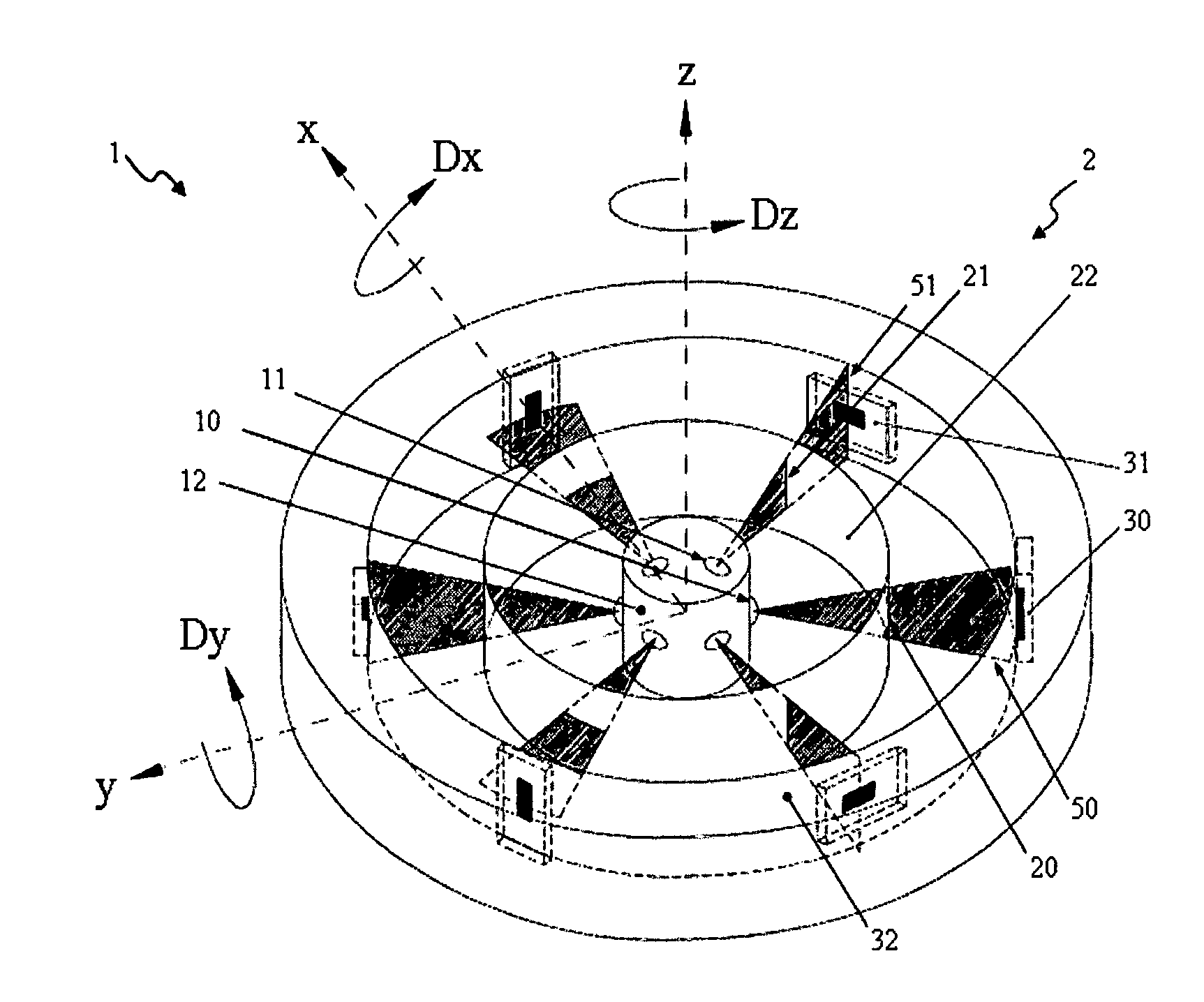
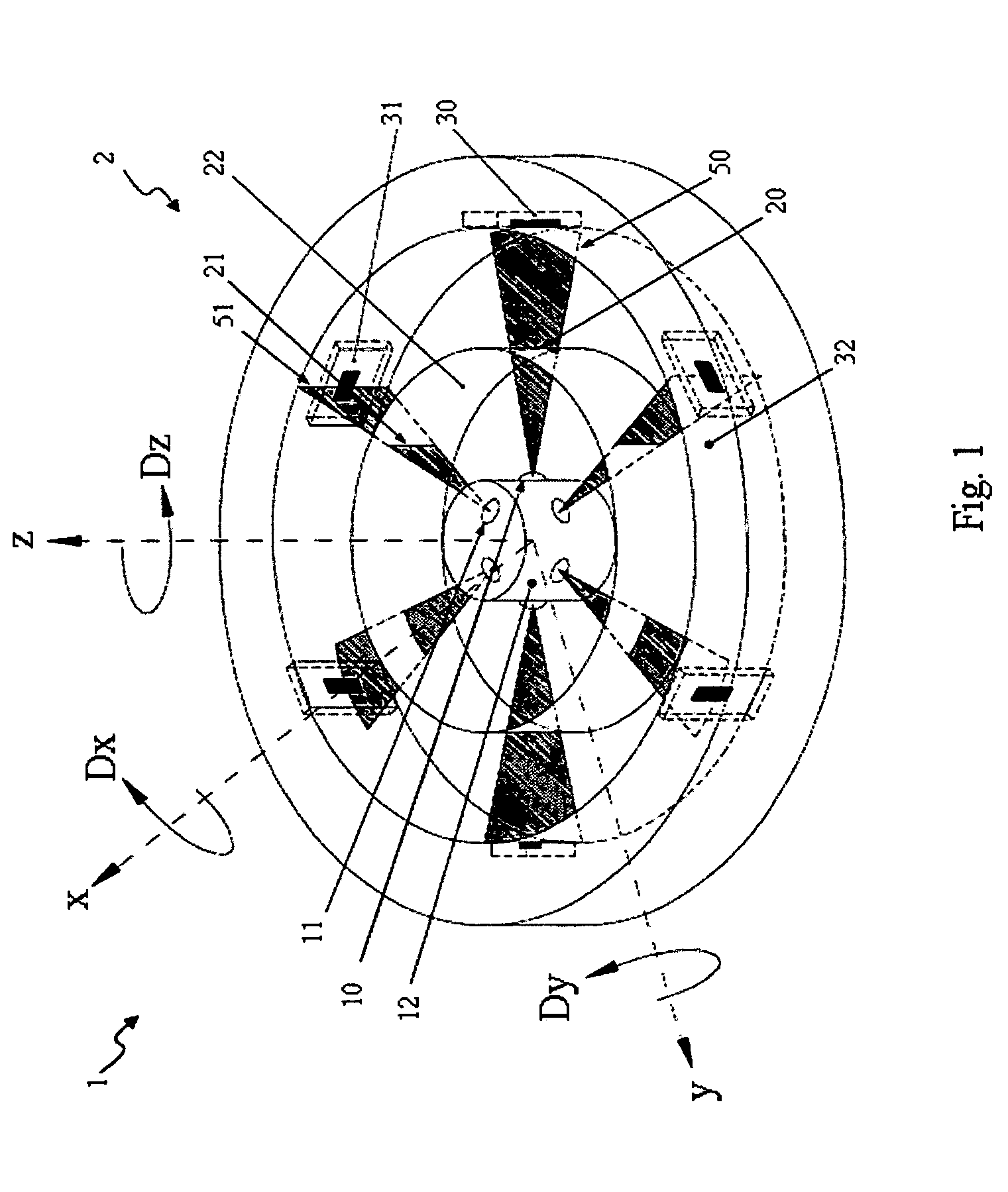
[0027]FIG. 1 shows a perspective view of an apparatus 1 for input of movements and / or registration of forces, which is designated in the following as 3D measuring system 1.

[0028]As can be recognised in FIG. 1, a basis measuring system 2 of 3D measuring system 1 comprises a light emitting diode (LED) 11, a slit diaphragm 21 and a linear position sensitive device (PSD) 31. Six of these basis measuring systems 2 are arranged in a plane, respectively shifted by 60 degrees, wherein the slit diaphragms 20, 21 and the PSDs 30, 31 are alternatingly rotated with respect to each other by 90 degrees, i.e. they are arranged in parallel or orthogonal to this plane. In other words, neighbouring slit diaph...


PUM


Abstract

The invention relates to an apparatus for input of movements and / or registration of forces, comprising at least one light source, at least one position sensitive device (PSD) and at least one diaphragm, wherein at least one of these three elements is moveable with respect to the two other elements. The light source is arranged at a mounting so that light from the light source is emitted through an opening in the mounting and through the at least one diaphragm onto the at least one PSD.

Description

1. TECHNICAL FIELD[0001]The invention relates to an apparatus for registering movements and forces.2. THE PRIOR ART[0002]Arrangements with opto-electronic measuring cells are conventionally used for registering relative movements or relative positions of two objects in force sensors and / or momentum sensors. The reason is the simple design in connection with high precision and reliability.[0003]DE 36 11 337 A1 discloses an opto-electronic arrangement in a plastic cap which can simultaneously register six components, namely translations along three axes and angular rotations around three axes. To this end, six light-emitting devices are arranged in a plane at equal angular distances. Each light-emitting device has a fixedly arranged slit diaphragm in front of it. The relative movements or relative positions are determined by light-sensitive detectors which are movably arranged with respect to the light-emitting devices and slit diaphragms and whose detector axis is essentially orthogo...

Claims


Application Information

Patent Timeline
Patent Type & Authority Applications(United States)
IPC IPC(8): G01B11/14
CPCG01L5/166G01D5/26
Inventor BECKER, FRANKENGELHARDT, MANFRED
Owner ABB (SCHWEIZ) AG
Why Eureka
Try Eureka