Expanded beam fiber optic connection system

Active Publication Date: 2010-02-04
GLENAIR
View PDF19 Cites 115 Cited by
  • Summary
  • Abstract
  • Description
  • Claims
  • Application Information

AI Technical Summary

Benefits of technology

[0015]Thus, there is a need for an expanded beam fiber optic interconnect which is a relatively less expensive replacement for existing phy

Problems solved by technology

While this method of optical fiber interconnect performs adequately, it has serious drawbacks in field deployment environments where contamination is a significant concern.
With such a minute transmission area, even microscopic airborne contaminants can easily obscure large sections of the core, significantly obstructing the optical path, resulting in signal loss.
Moreover, since the ferrules are in contact with each other, contaminants on the surface of either could permanently damage and contaminate

Method used


Image

  • Expanded beam fiber optic connection system
  • Expanded beam fiber optic connection system
  • Expanded beam fiber optic connection system

Examples


first embodiment

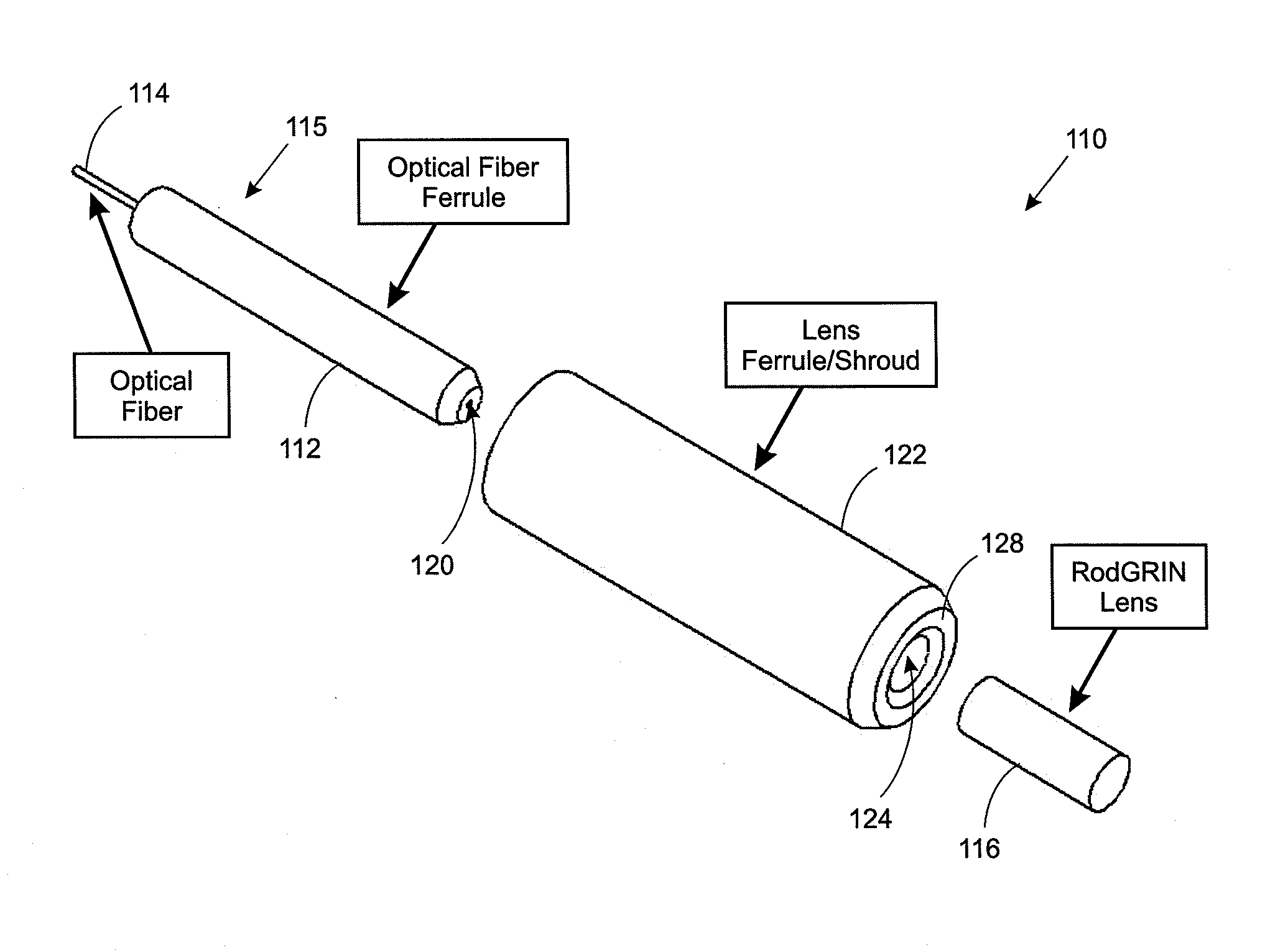
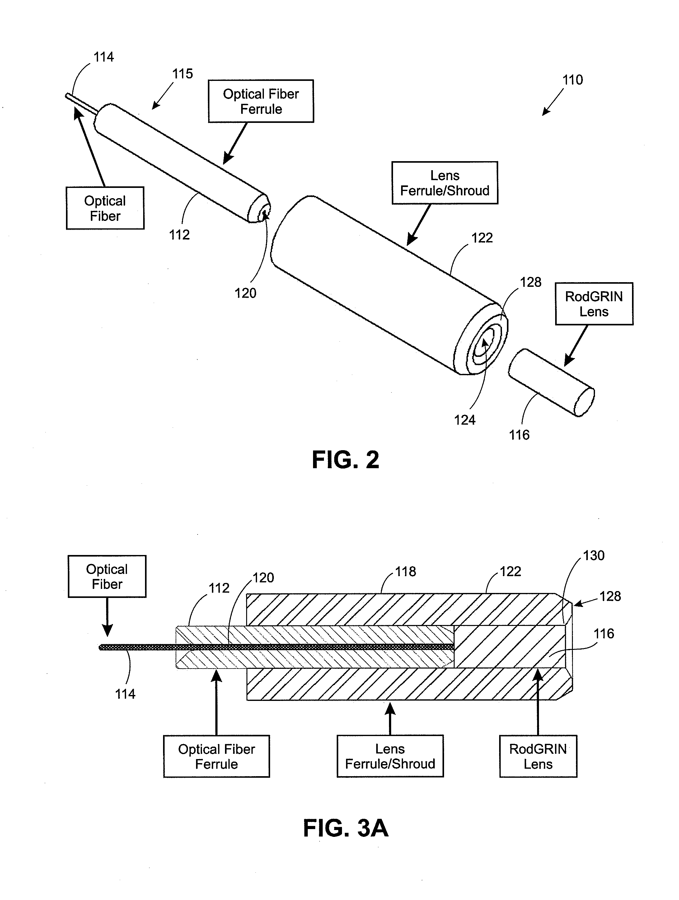
[0064]The first embodiment of the invention is illustrated in FIGS. 2-4G. Referring first to FIGS. 2, 3A, 4F and 4G, a first embodiment of the expanded beam fiber optic connector in accordance with the present invention is illustrated and generally identified with the reference numeral 110. The expanded beam fiber optic connector 110 includes an optical fiber ferrule 112 for carrying an optical fiber 114 forming a terminus. In accordance with an important aspect of the invention, expanded beam fiber optic connector 110 includes a GRIN lens 116. The GRIN lens 116 and the fiber optic ferrule 112 are concentrically aligned by way of a lens ferrule or shroud 118.

[0065]The optical fiber ferrule 112 is formed in a generally cylindrical shape. A central longitudinal feed through hole 120 is formed in the center of the optical fiber ferrule 112 for receiving an optical fiber 114. The through hole 118 is sized to have a diameter slightly larger than the diameter of the optical fiber 114. In ...

second embodiment

[0076]The second embodiment of the invention is illustrated in FIGS. 5-7. As mentioned above, in this embodiment, the outer ferrule diameter is used as the primary alignment feature between the termini, as discussed above. FIGS. 5, 6A and 7A illustrate a second embodiment of the invention with the rear body removed. FIGS. 6B and 7B illustrate the second embodiment of the invention with an exemplary one piece rear body. The second embodiment can also be implemented with other rear bodies, such as the two piece body discussed above.

[0077]The second embodiment of the expanded beam fiber optic terminus in accordance with the present invention is generally identified with the reference numeral 210. The expanded beam fiber optic terminus 210 includes an optical fiber ferrule 212 for carrying an optical fiber 214 forming a terminus 215. In accordance with an important aspect of the invention, the expanded beam fiber optic terminus 210 includes a GRIN lens 216.

[0078]The optical fiber ferrul...

third embodiment

[0083]The third embodiment is illustrated in FIGS. 8-10. The third embodiment is similar to the second embodiment in that the GRIN lens is aligned to the outer ferrule using an alignment sleeve. This design differs from the previous two because the termini are aligned with the alignment sleeve capturing the opposite end of the GRIN lenses as shown in FIGS. 9 and 10). The outer ferrule design is similar to the second as the GRIN lens is aligned to the ferrule using an alignment sleeve.

[0084]The third embodiment of the expanded beam fiber optic terminus in accordance with the present invention is generally identified with the reference numeral 310. The expanded beam fiber optic terminus 310 includes an optical fiber ferrule 312 for carrying an optical fiber 314 forming a terminus 315. In accordance with an important aspect of the invention, the expanded beam fiber optic terminus 310 includes a GRIN lens 316.

[0085]The optical fiber ferrule 312 is formed in a generally cylindrical shape...


PUM


Abstract

An expanded beam fiber optic connection system is disclosed which overcomes the problems associated with known expanded beam fiber optic connection systems. In particular, the expanded beam fiber optic connection system in accordance with the present invention includes a pair of mating fiber optic connectors. Each fiber optic connector includes a connector body and fiber optic termini. In accordance with an important aspect of the invention, the fiber optic termini utilize expanded beam technology and are configured with virtually the same form factor as existing physical contact fiber optic termini. The configuration of the expanded beam termini provides several benefits. First, existing physical contact fiber optic connection systems can be updated in the field by simply replacing the existing physical contact fiber optic termini with the new expanded beam fiber optic termini in accordance with the present invention and re-using the existing connector body, thus significantly reducing cost of upgrading existing physical contact type fiber optic connection systems. Secondly, since the same connector bodies are used for both the physical contact termini and the expanded beam termini, the number of components for the two types of fiber optic connection systems is reduced, thus reducing manufacturing costs.

Description

CROSS REFERENCE TO RELATED APPLICATIONS[0001]This application claims priority to and the benefit of U.S. Provisional Patent Application No. 61 / 084,387, filed on Jul. 29, 2008, hereby incorporated by reference.BACKGROUND OF THE INVENTION[0002]1. Field of the Invention[0003]The present invention relates to a fiber optic connection system for interconnecting optical fibers and more particularly an expanded beam fiber optic connection system that incorporates expanded beam fiber optic termini, which can be formed with relatively the same form factor as conventional physical contact fiber optic termini, that can be used to form fiber optic plugs, fiber optic receptacles and genderless, i.e. hermaphroditic connectors, as well as replace conventional physical contact fiber optic termini in existing connectors in the field in order to convert existing connectors with such conventional fiber optic termini to expanded beam technology.[0004]2. Description of the Prior Art[0005]Fiber optic syst...

Claims


Application Information

Patent Timeline
IPC IPC(8): G02B6/38
CPCB01L2400/0487B01L2300/087G02B6/3878G02B6/3825B01L2300/0887B01L3/502715B01L7/52G02B6/3821G02B6/3853B01L3/502753B01L3/50825B01L2200/027B01L3/5029B01L2300/0816B01L2200/16G02B6/3845B01L2300/0867G02B6/3887
Inventor ARMANI, DENIZ KDOSHI, MONISH J.NOLL, GREGORY B.SMITH, JONATHON M.
Owner GLENAIR
Why Eureka
Try Eureka