Turbine engine lubrication method and system

a technology for aviation turbomachines and lubricating methods, which is applied in the direction of non-positive displacement fluid engines, leakage prevention, pump control, etc., can solve the problems of increasing the weight of the turbomachine, consuming a large amount of lubricating oil, and reducing the efficiency of de-oiling, so as to achieve light weight and consume little oil or compressed air.

Inactive Publication Date: 2010-02-04
TECHSPACE AERO
View PDF9 Cites 43 Cited by
  • Summary
  • Abstract
  • Description
  • Claims
  • Application Information

AI Technical Summary

Benefits of technology

[0008]A main object of the present invention is thus to mitigate such drawbacks by proposing a lubrication method that is simplified, light in weight, and consumes little oil or compressed air.
[0010]The use of gravity and the pressurization of the enclosures for recovering all of the injected oil and oil makes it possible to avoid having recourse to recovery pumps such as those disclosed in the prior art. In addition, all of the oil and air injected into the enclosures is recovered via a single common air and oil circuit, thereby avoiding having recourse to a special circuit for removing and de-oiling the air introduced into the enclosures as described in the prior art. The method of lubrication is thus lighter and simpler.
[0011]According to the invention, the method consists in controlling the operation of the oil / air separator so as to operate it only when oil is present at its inlet. Controlling the oil / air separator thus makes it possible to save power.
[0012]In an advantageous disposition, the method also consists in controlling the operation of the oil feed pump to regulate the flow rate of oil conveyed to the enclosures as a function of the pressure and / or the temperature inside the enclosures. For this purpose, the oil feed pump may be started only when the temperature inside the enclosures rises above a given temperature. Controlling the pump makes it possible to avoid feeding the enclosures with oil when the oil / air mixture is no longer being recovered by gravity.

Problems solved by technology

Since providing lubrication merely by injecting oil during maintenance of the turbomachine is not sufficient, use is generally made of so-called “dynamic” lubrication.
In particular, it requires a large number of recovery pumps to be used (one pump per enclosure), thereby increasing the weight of the turbomachine.
Finally, it consumes a large amount of lubricating oil because the efficiency of de-oiling is a decreasing function of air flow rate.
That system also presents numerous drawbacks.
In particular it requires a pump to be present for recovering the oil / air mixture, thereby increasing the weight of the turbomachine.
Furthermore, that system applies only to the front enclosure of the turbomachine, with nothing being provided for lubricating other enclosures of the engine.

Method used


Image

  • Turbine engine lubrication method and system
  • Turbine engine lubrication method and system
  • Turbine engine lubrication method and system

Examples


Embodiment Construction

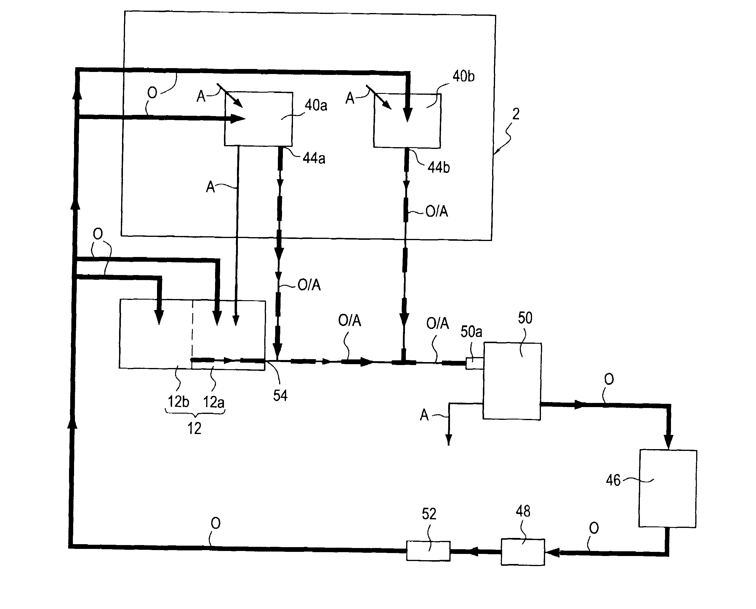
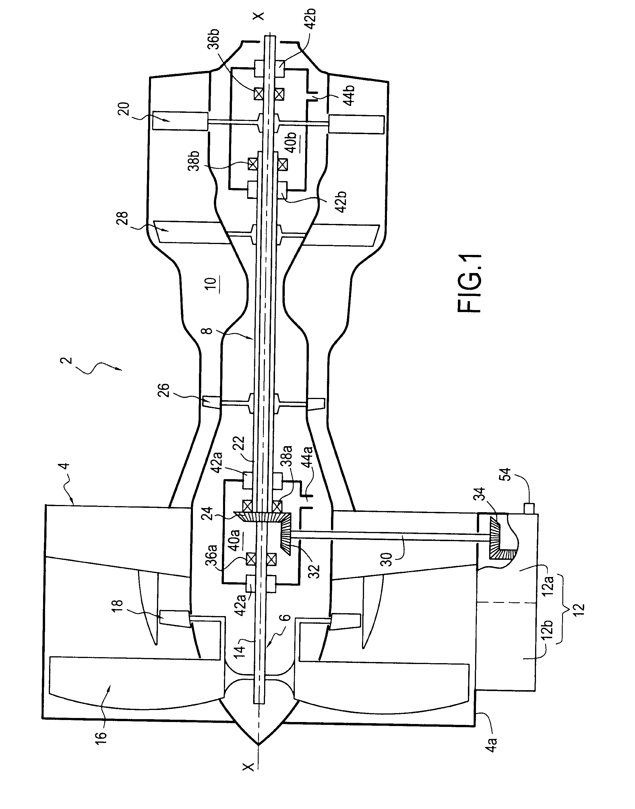
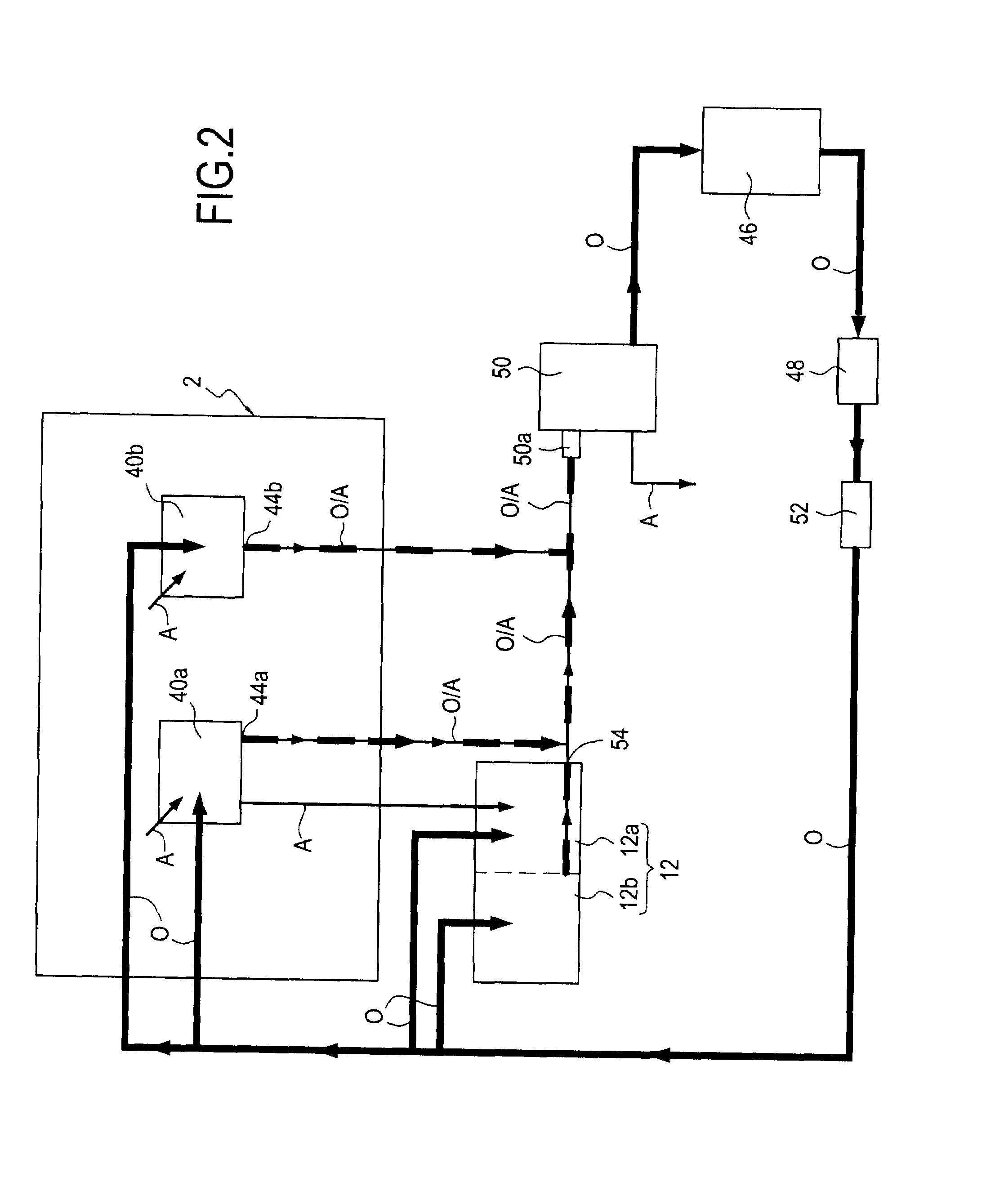
[0022]FIG. 1 is a diagram showing a portion of an aviation bypass turbomachine 2 in which the lubrication method and system of the invention can be implanted. Naturally, the present invention applies to any other type of turbomachine (single spool, triple spool, single-flow, industrial, etc.).

[0023]In well-known manner, the turbomachine 2 of longitudinal axis X-X comprises in particular a fan casing 4, a low-pressure spool 6, a high-pressure spool 8, a combustion chamber 10, and an accessory drive gearbox 12.

[0024]The low-pressure spool 6 comprises a low-pressure shaft 14 centered on the longitudinal axis X-X, a fan 16 mounted at the front end of the low-pressure shaft, a low-pressure compressor 18 fastened to the fan, downstream therefrom, and a low-pressure turbine 20 mounted on the rear end of the low-pressure shaft.

[0025]The high-pressure spool 8 comprises a high-pressure shaft 22 disposed concentrically around the low-pressure shaft 14, a bevel gear 24 mounted at the front end ...


PUM


Abstract

A method and a system for lubricating a turbomachine including an oil tank, an oil feed pump, an oil / air separator, and at least two enclosures closed by air flow rate seals, each including a low outlet and housing shaft-supporting rolling bearings. The method injects oil from the tank into the enclosures by the pump to lubricate the bearings, introduces compressed air at a low flow rate into the enclosures via the seals to pressurize the enclosures, recuperates all of the air and the oil introduced into the enclosures via their low outlet, uses gravity and the pressurization of the enclosures to convey the oil / air mixture as recovered in this way to the oil / air separator, separates the oil and the air of the mixture by the oil / air separator, returns the oil to the tank, and exhausts the air to outside the turbomachine.

Description

BACKGROUND OF THE INVENTION[0001]The present invention relates to the general field of lubricating an aviation turbomachine.[0002]An aviation turbomachine has numerous elements that need to be lubricated; these include in particular rolling bearings used for supporting the rotary shafts, and also the gearing, of the accessory drive gearbox.[0003]In order to reduce friction, wear, and heating due to the high speed of rotation of the turbomachine shafts, the bearings that support them need to be lubricated. Since providing lubrication merely by injecting oil during maintenance of the turbomachine is not sufficient, use is generally made of so-called “dynamic” lubrication.[0004]Dynamic lubrication consists in causing oil to circulate continuously in a lubrication circuit. A flow of lubricating oil from a tank is thus delivered to the bearings by a pump, which bearings are housed in enclosures that are closed by seals. In order to avoid lubricating oil leaking from the enclosures to the...

Claims


Application Information

Patent Timeline
Patent Type & Authority Applications(United States)
IPC IPC(8): F01D25/20F01D25/18
CPCF01D11/04F01D25/20F05D2240/50F16N7/385F02C7/06
Inventor CORNET, ALBERTRAIMARCKERS, NICOLAS
Owner TECHSPACE AERO
Why Eureka
Try Eureka