Polar modulation transmission apparatus

a transmission apparatus and modulation technology, applied in the direction of modulation, transmission monitoring, gain control, etc., can solve the problems of significant drift of transmission power, uncontrolled output power in uncompressed mode, and inability to accurately control output power, etc., to achieve accurate transmission power control

Active Publication Date: 2010-02-04
PANASONIC CORP
View PDF8 Cites 20 Cited by
  • Summary
  • Abstract
  • Description
  • Claims
  • Application Information

AI Technical Summary

Benefits of technology

[0016]It is therefore an object of the present invention to provide a polar modulation transmission apparatus that realizes accurate transmission power control in feedback control of the output power of a power amplifier.

Problems solved by technology

In this uncompressed mode, given that the PA operates in the linear region, the output power is not controlled as accurately as in compressed mode.
As shown in FIG. 2, given that the output power in uncompressed mode is likely to drift due to various factors, when compressed mode and uncompressed mode are switched, the output power in uncompressed mode is likely to be discontinuous, and, as a result, significant drift of transmission power is likely to occur.
On the other hand, if the time constant of a low-pass filter is set bigger, the response of the low-pass filter becomes poorer, and, accompanying this, the responsivity of feedback control becomes poorer.
Given that there are wireless communication standards that require completing transmission power control in a very short period, in practice, the time constant of the low-pass filter cannot be set too big.
Particularly, when the above compressed mode and uncompressed mode are switched, feedback control of a higher rate is needed, and so it becomes even more difficult to make the time constant of the low-pass filter big.

Method used


Image

  • Polar modulation transmission apparatus
  • Polar modulation transmission apparatus
  • Polar modulation transmission apparatus

Examples


Embodiment Construction

[0048]Embodiments of the present invention will be described in detail with reference to the accompanying drawings.

(1) Overall Configuration

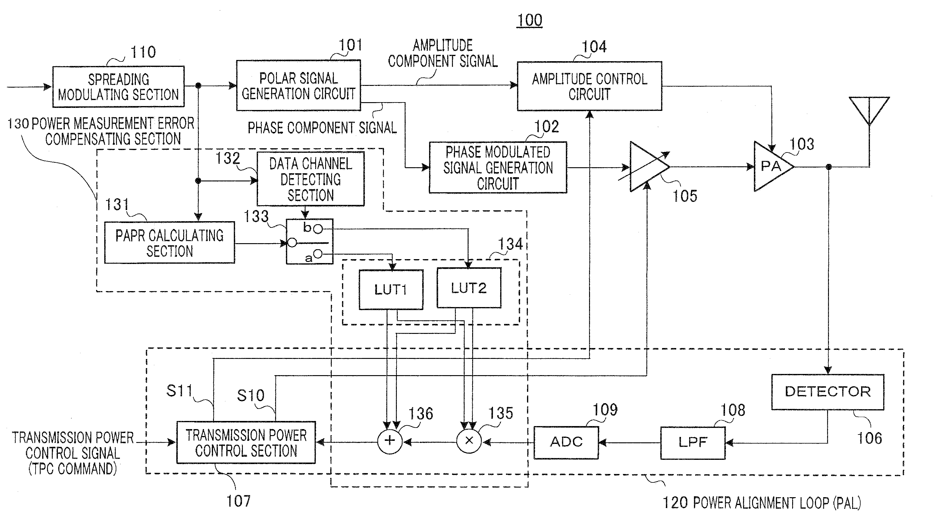
[0049]FIG. 3 shows the configuration of the polar modulation transmission apparatus according to an embodiment of the present invention. Polar modulation transmission apparatus 100 of FIG. 3 has polar signal generation circuit 101, phase modulated signal generation circuit 102, power amplifier (PA) 103, amplitude control circuit 104, variable amplifier 105 formed with a variable gain amplifier (VGA) and / or an attenuator, and power alignment loop (PAL) 120.

[0050]Power alignment loop 120 has detector 106 that detects the output power of PA 103, low-pass filter (LPF) 108, analogue-to-digital converter (ADC) 109 and transmission power control section 107.

[0051]Further, in power alignment loop 120, arithmetic operators (multiplier 135 and adder 136) which are part of the components of power measurement error compensating section 130 (described later)...


PUM


Abstract

By compensating for a detection result of the detector in feedback control of output power of the power amplifier, the polar modulation transmission apparatus is able to realize accurate transmission power control. Polar modulation transmission apparatus 100 has detector 106 that detects output power of power amplifier 103, PAPR calculating section 131 that calculates the PAPR of the spread modulated signal, compensation value generating section 134 that outputs a compensation value corresponding to the calculated PAPR and an arithmetic operator that performs an arithmetic operation using the compensation value and a detection result obtained by detector 106. By this means, it is possible to compensate for the sensitivity of detector 106 (measurement sensitivity) that changes depending on the B parameter and mode and make the sensitivity of detector 106 (measurement sensitivity) virtually constant.

Description

BACKGROUND OF THE INVENTION[0001]1. Field of the Invention[0002]The present invention relates to a technique of reducing the output power difference in a polar modulation transmission apparatus.[0003]2. Description of the Related Art[0004]FIG. 1 shows an example of a typical transmission apparatus using a polar modulation scheme. The transmission apparatus has polar signal generation circuit 1, amplitude control circuit 2, phase modulated signal generation circuit 3 and power amplifier (hereinafter “PA”) 4. In this transmission apparatus, polar signal generation circuit 1 generates an amplitude component signal and a phase component signal of a modulated transmission signal from an input signal (i.e. the modulated transmission signal). Amplitude control circuit 2 controls the power supply voltage supplied to PA 4 based on the amplitude component signal, and phase modulated signal generation circuit 3 generates a phase modulated signal inputted to PA 4 based on the phase component si...

Claims


Application Information

Patent Timeline
Patent Type & Authority Applications(United States)
IPC IPC(8): H04B1/04
CPCH03G3/3042H03G3/3047H04B2001/0416H04B1/0483H04B1/0475
Inventor URUSHIHARA, TOMOYAMATSUOKA, AKIHIKO
Owner PANASONIC CORP
Why Eureka
Try Eureka