Bypass system to control liquid volume

a liquid volume control and bypass technology, applied in the direction of water supply tanks, pumping plants, domestic plumbing, etc., can solve the problems of reducing the volume, and affecting the bathing experien

Inactive Publication Date: 2010-02-11
MAAX BATH
View PDF28 Cites 14 Cited by
  • Summary
  • Abstract
  • Description
  • Claims
  • Application Information

AI Technical Summary

Benefits of technology

[0014]The controlled-flow valve allows varying volumes of water or fluid to be directed through the main reservoir loop and the bypass loop. This in turn affects the pressure of the fluid as it is released or discharged through the jets of a bathing vessel, resulting in an effect that can be adjusted in accordance with the bather's needs or desires.

Problems solved by technology

This is a disadvantage for a bather who may wish to adjust the velocity or flow of water that is discharged through the jets of the bathing vessel.
If a pressure switch is used when there is not enough liquid pressure in the system, the switch can be tripped and the motor stopped in this way.
In addition, while choking the outlet does result in a reduction of the volume of water running through the bathing vessel, it also increases the noise level of the whole system.
This is an undesirable side effect.
These approaches can be difficult to implement, and they can be expensive.
Inconveniently, some of the means suggested above do not allow regulation of the water flow or pressure by the bather.
In addition, some of them result in the creation of an audible noise, which can lessen the enjoyment of the bathing experience.

Method used


Image

  • Bypass system to control liquid volume
  • Bypass system to control liquid volume
  • Bypass system to control liquid volume

Examples


first embodiment

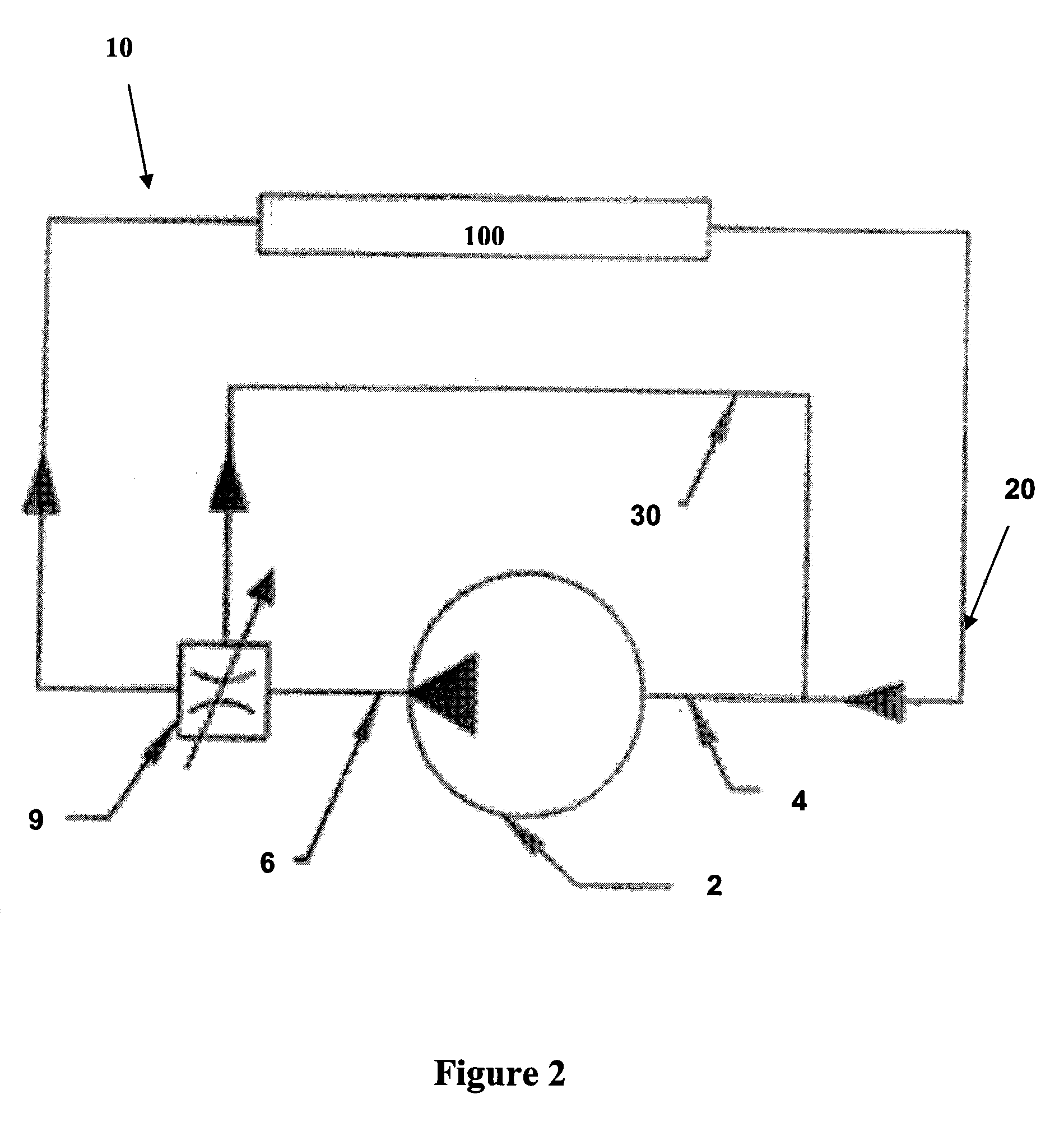
[0029]As may be seen in FIG. 2, which represents the present invention, the valve 9 is close to the outlet 6 of the pump 2 at a junction between the main loop 20 and the bypass loop 30. This valve 9 is a three-way valve which can divert, in different percentages, the liquid to the main loop 20 or the bypass loop 30.

second embodiment

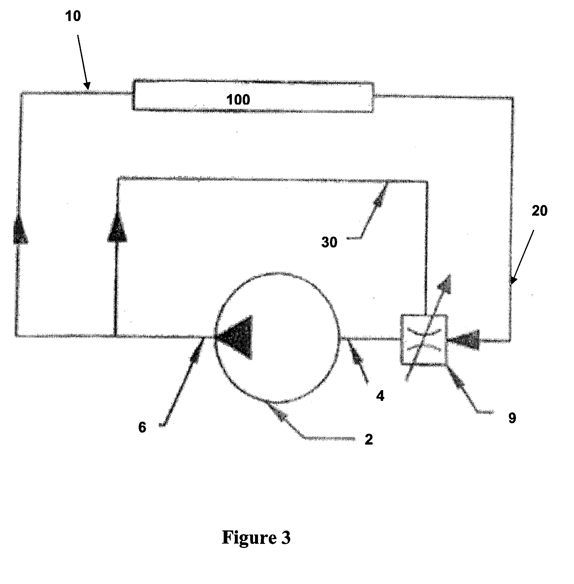
[0030]Turning now to FIG. 3, which shows the present invention, the valve 9 is close to the inlet 4 of the pump 2 at a junction between the main loop 20 and the bypass loop 30. This valve 9 is also three-way valve which can divert, in different percentage, the liquid to the main loop 20 or the bypass 30. The advantage of the configuration of this system is that even if the valve is in the intake side of the pump, the pump remains filled with liquid at all times, with the result that the efficiency or the cooling of the liquid-cooled motor remains unaffected by variations in water flow.

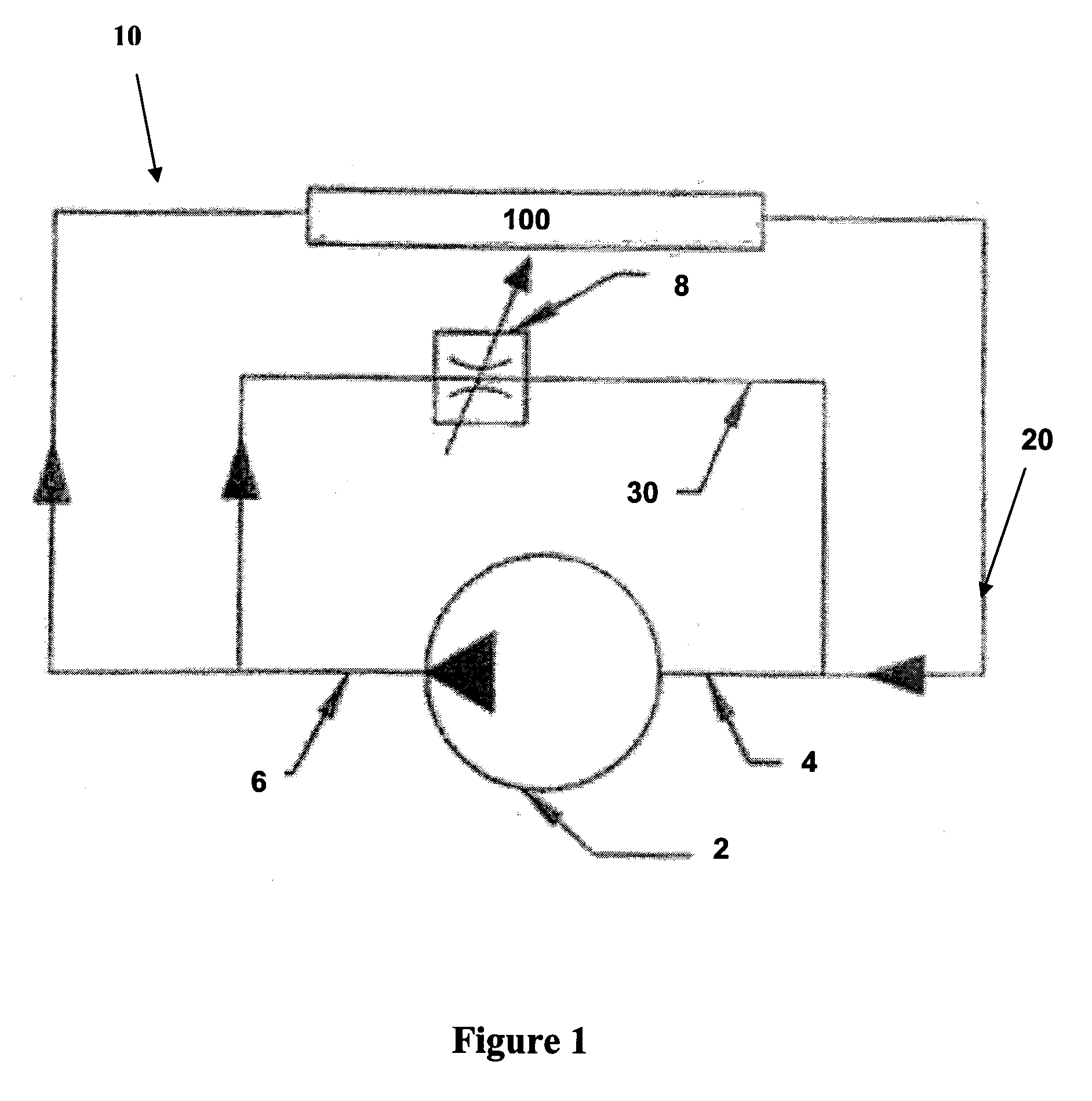
[0031]FIG. 4 shows a slightly more intricate arrangement of the bypass system illustrated in FIG. 1. Once again, the bypass system is shown generally by the numeral 10. The main and bypass loops are represented by the numerals 20 and 30, respectively. The pump 2 is preceded by an inlet 4 and followed by an outlet 6, and the valve and reservoir identified by the numerals 8 and 100, respectively. This ar...

third embodiment

[0032]the invention is shown in FIG. 5. The bypass system is represented generally by the numeral 10. This embodiment very closely resembles the embodiment illustrated in FIG. 2 by having a tri-way valve 9 positioned close to the outlet 6 of the pump 2. The inlet 4, main loop 20, bypass loop 30 and reservoir 100 are approximately in the same positions as in FIG. 2. An additional element of flow control has been introduced by including a second valve 8 in a new plumbing connection (or “bridge” element) 40 that has been established between the reservoir 100 and the bypass loop 30. This in effect allows an unlimited number of possibilities for varying the quantity of liquid entering the reservoir 100. The liquid inlet 40 in the reservoir 100 can supply a different function in the reservoir and have different pressure while still being supplied by only one pump. A variation of this embodiment would involve repositioning and replacement of the second valve 8, which is a two-way valve, by...


PUM


Abstract

The present invention relates a novel bypass system to control liquid volume. More particularly, the invention relates to a system for use in the control and regulation of pumps, pumping installations and/or systems, and the control of fluid flow in general. This system will find particular, though not exclusive, application with bathing vessels such as pools, whirlpools, bathtubs, hot tubs and spas.

Description

CROSS REFERENCE TO RELATED APPLICATION[0001]This application is a claims the benefit of U.S. Provisional Patent Application No. 61 / 086,624 filed Aug. 6, 2008 the entirety of which is hereby incorporated by reference into this application.FIELD OF THE INVENTION[0002]The present invention relates a novel bypass system to control liquid volume. More particularly, the invention relates to a system for use in the control and regulation of pumps, pumping installations and / or systems, and the control of fluid flow in general. This system will find particular, though not exclusive, application with bathing vessels such as pools, whirlpools, bathtubs, hot tubs and spas.BACKGROUND OF THE INVENTION[0003]Bathing vessels such as spas and hot tubs are very popular and commercially successful. These vessels are water holding enclosures (or reservoirs) that are typically constructed from a molded shell. The molded enclosures include one or more bathing spaces for use by one or more persons, and eac...

Claims


Application Information

Patent Timeline
Patent Type & Authority Applications(United States)
IPC IPC(8): E03B5/00
CPCA61H33/0087E04H4/12A61H33/60F15B2211/40515F15B2211/41509F04D15/0011Y10T137/85978
Inventor LEMIRE, GUYGAMACHE, FRANCOIS
Owner MAAX BATH
Why Eureka
Try Eureka