Gas wiping apparatus having multiple nozzles

a gas wiping and nozzle technology, applied in the direction of liquid surface applicators, coatings, metallic material coating processes, etc., can solve the problems of increasing the collision pressure, increasing the ejection speed of gas, and gas being ejected with non-uniform distribution along the width direction of steel strips, so as to increase the productivity of coating processes, effective prevent splashing, and stably spray

Active Publication Date: 2010-02-11
POHANG IRON & STEEL CO LTD
View PDF8 Cites 4 Cited by
  • Summary
  • Abstract
  • Description
  • Claims
  • Application Information

AI Technical Summary

Benefits of technology

[0037]In a multi-nozzle gas wiping apparatus according to the invention, the surface of a steel strip passing through a hot dipping bath filled with a molten metal is wiped by a high speed gas jet. Meanwhile, zinc chips are effectively prevented from splashing even during a high speed coating, thereby increasing productivity of the coating process.
[0038]Moreover, multiple uniform pressure spaces (chambers) are formed inside the gas wiping apparatus to ensure a gas jet to be sprayed uniformly through the multiple nozzle unit along a width direction of the steel sheet. Also, turbulent components of the jet are inhibited to ensure the jet to be sprayed stably.
[0039]Therefore, the gas wiping apparatus having the multiple nozzle unit prevents zinc chips from splashing by adjusting a coating thickness of the steel sheet. This also allows the gas to be ejected uniformly along a width direction of the steel sheet, ultimately enhancing coating quality of the steel strip.

Problems solved by technology

Therefore, this requires gas to move at a higher speed, thereby increasing a collision pressure.
However, as described above, the higher speed of the gas ejected proportionally aggravates splashing of the zinc chips so that the gas is limitedly increased in its ejection speed.
The zinc chips d splashed as described above are deposited on or around the outlets of the gas wiping apparatus, causing the gas to be ejected with non-uniform distribution along a width direction of the steel strip.
This results in defective coating of the steel strip.
Therefore, to restrain the molten metal from splashing during thin coating, currently the steel strip moves at a lower speed to be coated, thus limiting a high-speed travel of the steel strip and eventually degrading production of the steel strip.

Method used


Image

  • Gas wiping apparatus having multiple nozzles
  • Gas wiping apparatus having multiple nozzles
  • Gas wiping apparatus having multiple nozzles

Examples


Embodiment Construction

[0054]The present invention will now be described in detail.

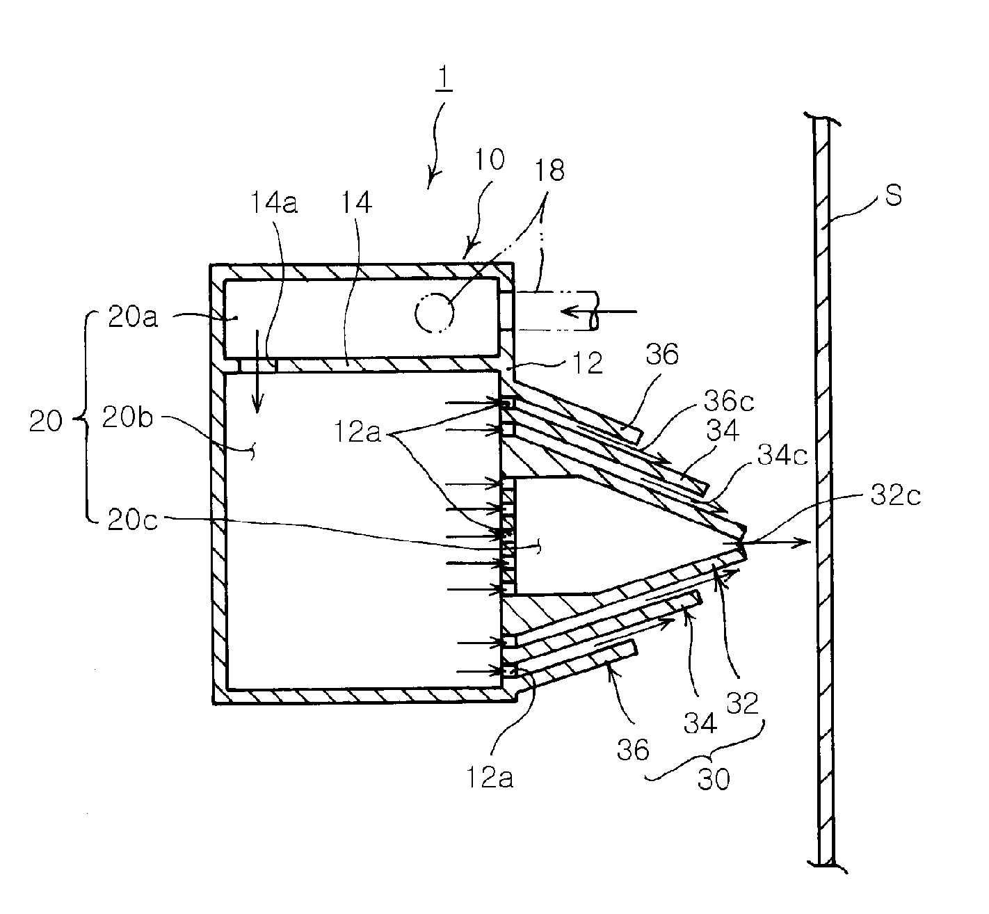
[0055]A gas wiping apparatus (or an air knife) adjusts a coating thickness of a steel strip. In the gas wiping apparatus, a high-pressure gas (air or inactive gas) is blown at a high speed through a nozzle thereof to collide against a steel strip, thereby generating a collision pressure.

[0056]Here, the higher pressure of the gas sprayed causes gas particles to move more dynamically, thereby wiping a coating layer of the steel strip to a small thickness.

[0057]Also, as the steel strip travels faster, more gas should participate in wiping per unit time so that the gas should be ejected at a higher pressure or at a higher speed.

[0058]For example, when it comes to a gas wiping for adjusting a coating thickness of the steel strip, the coating thickness is varied according to a moving speed of the steel strip, a pressure and speed of the gas sprayed from the nozzle and a gap between the steel strip and the nozzle.

[0059]However, in...


PUM

PropertyMeasurementUnit
pressureaaaaaaaaaa
thicknessaaaaaaaaaa
corrosion-resistantaaaaaaaaaa

Abstract

A gas wiping apparatus is a type of equipment for coating a molten metal onto a steel strip, in which the molten metal solution deposited on the steel strip is wiped to adjust a coating thickness. The gas wiping apparatus includes a body containing a high pressure gas and a multiple nozzle unit disposed at the body to eject the high pressure gas onto a surface of a moving coated steel strip. The surface of the coated steel strip passing through a hot dipping bath filled with the molten metal is wiped by a high speed gas jet. Here, the molten metal is prevented from splashing even at a high-speed and the steel strip can be adjusted in the coating thickness stably and uniformly.

Description

TECHNICAL FIELD[0001]The present invention relates to a gas wiping apparatus for coating a molten metal such as molten zinc on the surface of a steel strip, in which the molten metal solution deposited on the steel strip is wiped to adjust a coating thickness of the steel strip. More particularly, the present invention relates to a multi-nozzle gas wiping apparatus which can wipe the surface of the coated steel strip passing through a hot dipping bath filled with a molten metal by a high speed gas jet to restrain the molten metal from splashing even at a high-speed and adjust a coating thickness (coating thickness) of the coated steel strip stably and uniformly.BACKGROUND ART[0002]A steel strip, especially a coated steel strip obtained by coating a specific molten metal, e.g., molten zinc onto a cold-rolled steel strip, is highly corrosion-resistant and has aesthetic appearance.[0003]Especially, lately, this coated steel strip has been utilized in electronic products or automobiles,...

Claims


Application Information

Patent Timeline
Patent Type & Authority Applications(United States)
IPC IPC(8): C23C2/16
CPCC23C2/20C23C2/003C23C2/06C23C2/16C23C2/26C23C2/40
Inventor KIM, GUN YOUNGPARK, HAE DOOLEE, DONG EUNCHUNG, WON CHEOL
Owner POHANG IRON & STEEL CO LTD
Why Eureka
Try Eureka