
Spark Plug for an internal combustion engine and method for the operation thereof

a technology of internal combustion engine and spark plug, which is applied in the direction of spark plugs, machines/engines, mechanical equipment, etc., can solve the problems that the above-described known method of ascertaining optical operating data from the spark plug or from the combustion chamber associated therewith is not usable with conventional spark plugs that have an integrated ignition laser, and achieves a simple and flexible evaluation of operating data

Inactive Publication Date: 2010-02-11
ROBERT BOSCH GMBH
View PDF3 Cites 18 Cited by
  • Summary
  • Abstract
  • Description
  • Claims
  • Application Information

AI Technical Summary

Benefits of technology

[0005]It is accordingly an object of the present invention to improve a spark plug and an operating method of the kind cited above in such a way as to make possible simpler and more flexible evaluation of operating data of the spark plug.
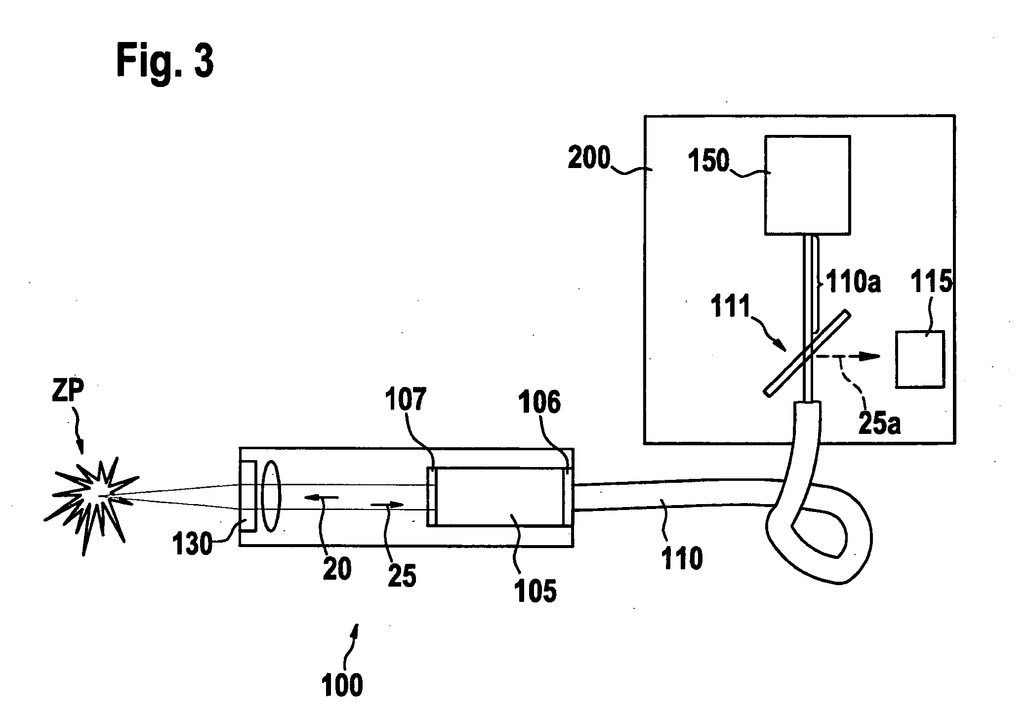
[0008]As a further manner of achieving the object of the present invention, a spark plug according to Claim 7 is indicated. The spark plug, having an integrated ignition laser, is characterized in that the ignition laser is at least partially transparent to light of a first wavelength region that is radiated from a combustion chamber into the spark plug, the first wavelength region may be extending from approximately 200 nm to approximately 800 nm; and that the light guide device has associated with it an optical beam splitter for separating light of the first wavelength region from the pump light. Because the ignition laser and its components are embodied, according to the present invention, to be transparent to a wavelength region of interest of optical operating data, a physically small configuration can be achieved even with such spark plug types, and at the same time enables optical monitoring of operation of the spark plugs and of processes in the combustion chamber.

Problems solved by technology

In addition, the above-described known manner of ascertaining optical operating data from the spark plug or from a combustion chamber associated therewith is not usable with conventional spark plugs that have an integrated ignition laser.

Method used


Image

  • Spark Plug for an internal combustion engine and method for the operation thereof
  • Spark Plug for an internal combustion engine and method for the operation thereof
  • Spark Plug for an internal combustion engine and method for the operation thereof

Examples


Embodiment Construction

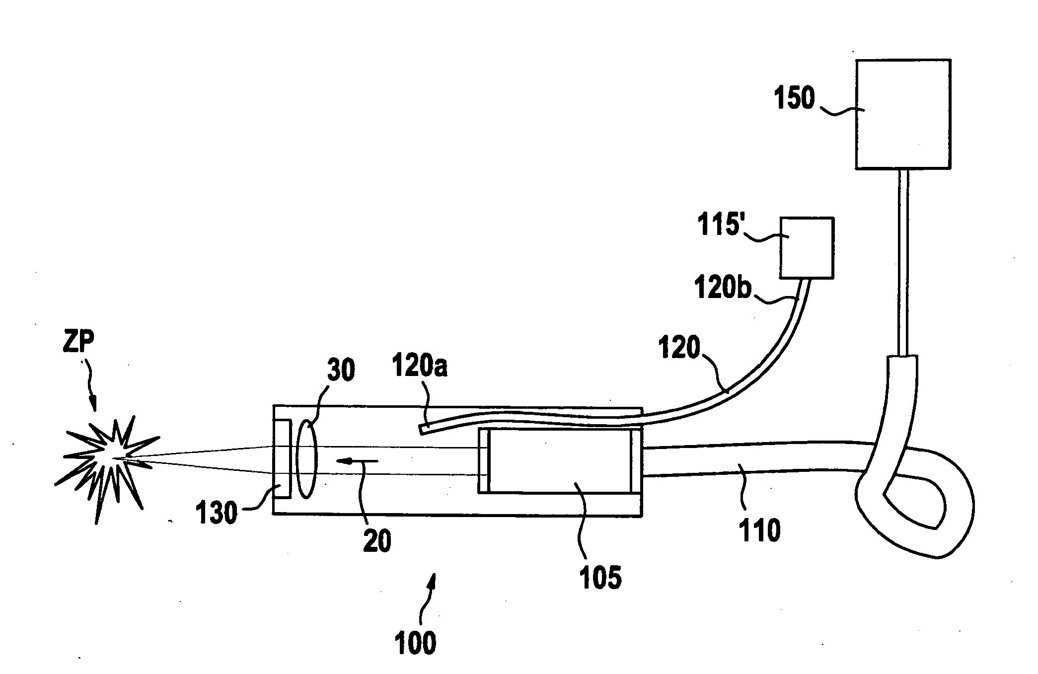
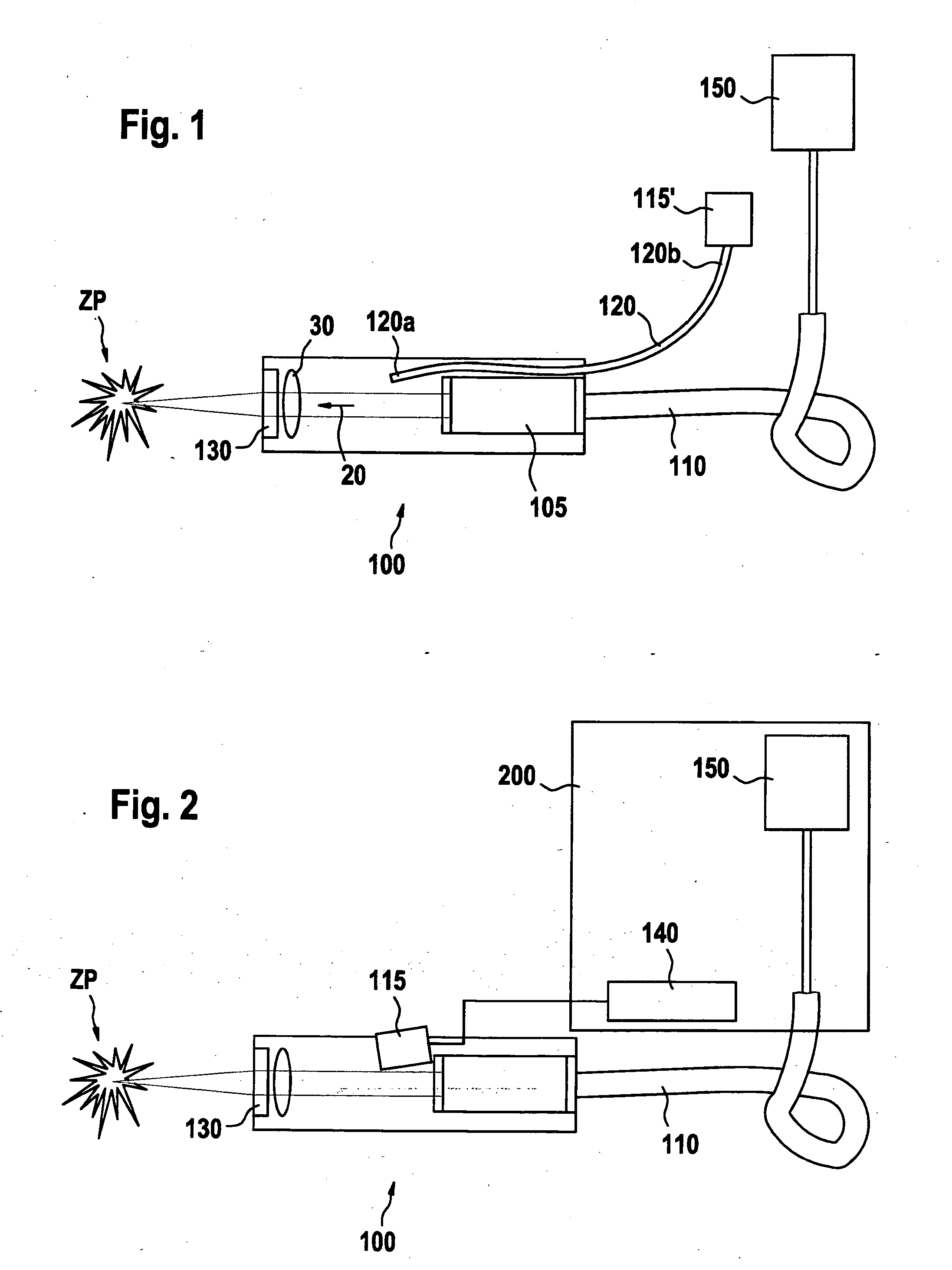
[0015]FIG. 1 schematically depicts a spark plug 100 according to the present invention for an internal combustion engine. Spark plug 100 has a light guide device 110, embodied in the present case as a light-guiding fiber, that supplies spark plug 100 with light that is made available by a light source 150.

[0016]Light source 150 can be, for example, a pump light source that supplies pump light to a laser-active solid 105, provided in spark plug 100, of an integrated ignition laser. Ignition laser thereupon, in known fashion, generates laser pulses (cf. arrow 20) that are emitted through combustion chamber window 130, disposed at a left end (in FIG. 1) of spark plug 100, into an adjacent combustion chamber of the internal combustion chamber. An optical system, symbolized in the present case by lens 30, can be provided in order to focus laser pulses 20 onto an ignition point ZP located in the combustion chamber, and onto fuel present in that region.

[0017]A sensor arrangement is provide...


PUM


Abstract

A spark plug for an internal combustion engine having a light guide device for supplying the spark plug with optical radiant power. A sensor arrangement is at least partially integrated into the spark plug but disposed outside the light guide device, and is embodied for the acquisition of operating data of the spark plug and / or of a combustion chamber associated with the spark plug.

Description

FIELD OF THE INVENTION[0001]The present invention relates to a spark plug for an internal combustion engine having a light guide device for supplying the spark plug with optical radiant power. The present invention further relates to a method for operating a spark plug of this kind.BACKGROUND OF THE INVENTION[0002]An ignition device having a laser is discussed in DE 199 11 737 or DE 101 45 944.[0003]Spark plugs and operating methods of the kind cited above are used in particular in laser-based ignition systems of internal combustion engines. It is known to use the light guide device provided for supplying the spark plug with optical radiant power, such as pump light, to acquire optical operating data of a combustion chamber associated with the spark plug, or of the spark plug itself. In this context, optical operating data are correspondingly transferred from the combustion chamber via the light guide device to an evaluation apparatus, usually necessitating a separation of said opti...

Claims


Application Information

Patent Timeline
IPC IPC(8): F02P23/04H01T13/02F02P17/12
CPCF02P17/12G01M15/10F02P23/04
Inventor HERDEN, WERNERVOGEL, MANFREDRIDDERBUSCH, HEIKO
Owner ROBERT BOSCH GMBH
Learn More