Data communication system, data carrier driving apparatus, and data carrier apparatus

Active Publication Date: 2014-06-19
CANON KK
View PDF2 Cites 7 Cited by
  • Summary
  • Abstract
  • Description
  • Claims
  • Application Information

AI Technical Summary

Benefits of technology

[0011]The present invention can provide a technique to realize stable data communication between a data carrier driving apparatus a

Problems solved by technology

However, the above conventional technique has the following problem.
When a microcomputer and a highly-functional memory chip are used in a circuit in a data carrier apparatus, this circuit shall be configured using discrete components; this could possibly restrict the space for arranging components in realization of a small data carrier apparatus.
However, if a peak value of a charging current increases during an operation for charging a capacitor (capacitance element) used in the rectification smoothing circuit, a relatively large cur

Method used


Image

  • Data communication system, data carrier driving apparatus, and data carrier apparatus
  • Data communication system, data carrier driving apparatus, and data carrier apparatus
  • Data communication system, data carrier driving apparatus, and data carrier apparatus

Examples


first embodiment

[0020]The following describes a first embodiment of the present invention with reference to FIGS. 1, 2 and 4 to 6. First, a description will be given of a comparative example with respect to the first embodiment and a later-describe second embodiment with reference to FIGS. 4 to 6, so as to facilitate the understanding of these embodiments.

Comparative Example of Data Communication System

[0021]FIG. 4 shows a configuration of a data communication system that serves as a comparative example with respect to the embodiments of the present invention. As shown in FIG. 4, the data communication system includes a data carrier driving apparatus 2 and a data carrier apparatus 3, which can perform bidirectional data communication only via two contacts 20 and 30 for the purpose of downsizing the system. An electric circuit 8 in the data carrier apparatus 3 is formed as one semiconductor chip.

[0022]The data carrier driving apparatus 2 has two terminals A and B. On the other hand, the data carrier...

second embodiment

[0075]A second embodiment realizes stable data communication between data carrier driving apparatus 102 and data carrier apparatus 103 by suppressing a decrease in the amplitude of the pulse voltage VA using a different method from the first embodiment. The following describes the second embodiment of the present invention with reference to FIG. 3. Note that configurations of the data carrier driving apparatus 102 and the data carrier apparatus 103 according to the second embodiment are similar to those according to the first embodiment. For simplicity, a description of portions that are similar to the first embodiment is omitted below; the following describes portions that are different from the first embodiment.

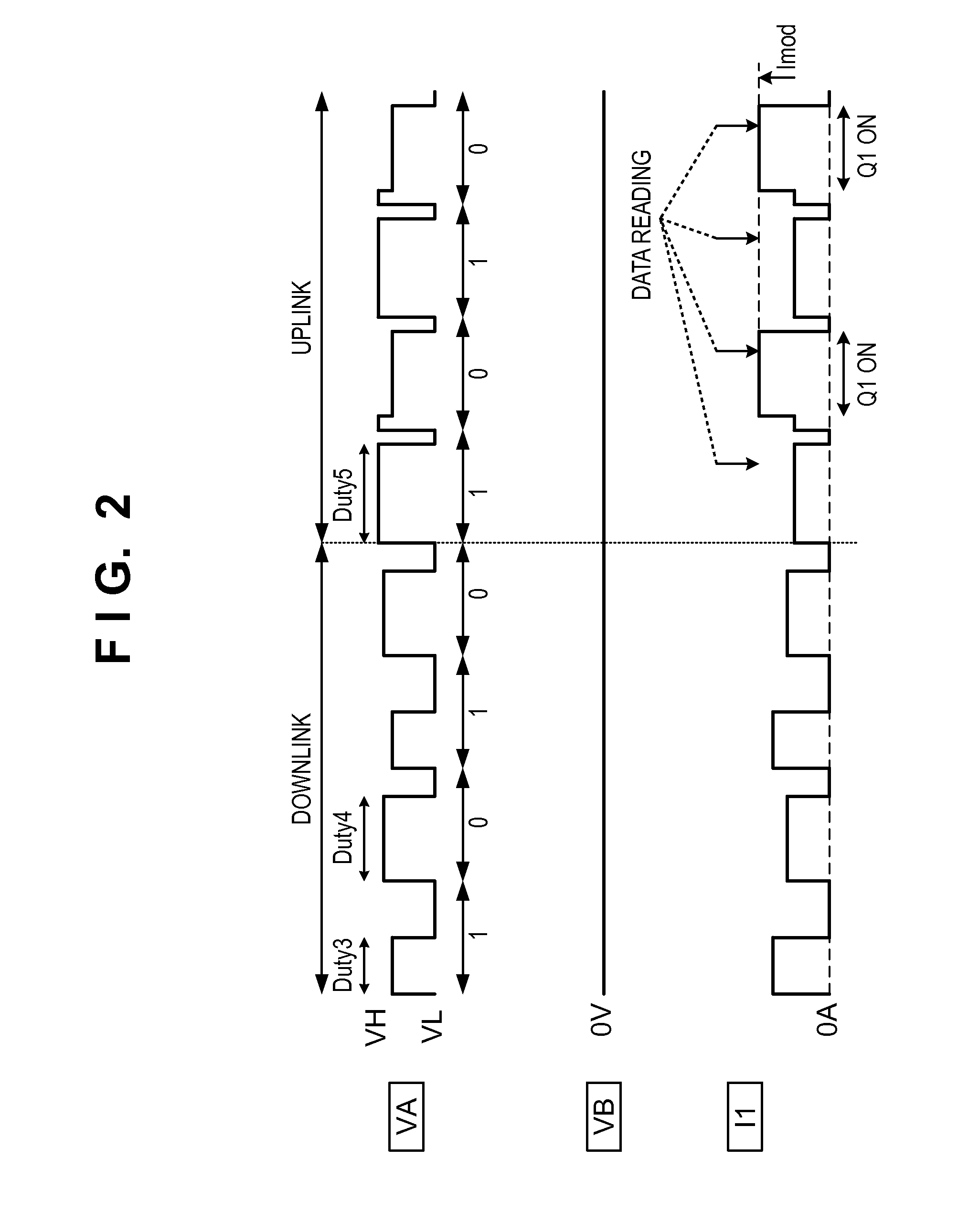
[0076]In the first embodiment, as shown in FIG. 2, a transmission period for transmitting each data is made up of a time frame in which the pulse voltage VA is a high-level voltage (VH) and a subsequent time frame in which the pulse voltage VA is a low-level voltage (VL) fo...


PUM


Abstract

In a data communication system according to one aspect of the present invention, a data carrier driving apparatus, which communicates with a data carrier apparatus using a rectification smoothing circuit for generating a power supply voltage, controls a pulse width of each pulse of a clock signal (pulse voltage) supplied to the data carrier apparatus. The data carrier driving apparatus sets the duration of each pulse of a pulse voltage generated by the data carrier driving apparatus, so as to suppress a decrease in the level of the pulse voltage caused by a charging operation for the rectification smoothing circuit, particularly, such that the duration in which the pulse voltage becomes a high-level voltage is longer than or equal to the duration in which the pulse voltage becomes a low-level voltage during one period.

Description

BACKGROUND OF THE INVENTION[0001]1. Field of the Invention[0002]The present invention relates to a data communication system including a data carrier driving apparatus and a data carrier apparatus, and in particular to data communication between the data carrier driving apparatus and the data carrier apparatus.[0003]2. Description of the Related Art[0004]Japanese Patent No. 4393351 describes an example of a configuration that, in a system in which a data carrier driving apparatus and a data carrier apparatus perform data communication, enables bidirectional data communication via two contacts for the purpose of downsizing the system. In order to further improve the versatility of the data carrier apparatus in the data communication system described in Japanese Patent No. 4393351, a generous-purpose microcomputer and a highly-functional memory chip may be used in a circuit in the data carrier apparatus.[0005]However, the above conventional technique has the following problem. When a ...

Claims


Application Information

Patent Timeline
IPC IPC(8): H04L25/49
CPCH04L25/4902
Inventor KARINO, KENICHI
Owner CANON KK
Why Eureka
Try Eureka