
Antenna configuration

a technology for antenna configuration and telecommunication devices, applied in the direction of resonant antennas, independent non-interaction antenna combinations, protective materials radiating elements, etc., can solve the problem of shrinking the size of the antenna configuration, and achieve the effect of increasing bandwidth, small antenna configuration, and increasing bandwidth

Active Publication Date: 2010-11-09
NXP BV
View PDF9 Cites 8 Cited by
  • Summary
  • Abstract
  • Description
  • Claims
  • Application Information

AI Technical Summary

Benefits of technology

The invention provides an antenna configuration for telecommunication devices that can be used in handheld devices and contactless operating data carriers, like smart cards. The antenna configuration includes a first resonator structure and a second resonator structure that are capacitive coupled to each other, and a control electrode that can change the capacitive coupling between the two resonator structures. The control electrode can be contacted from outside the antenna configuration, and a switching means is associated with it for switching the resonance frequency of the antenna configuration. The invention solves the problem of limited bandwidth in small antenna configurations by providing a way to change the resonance frequency, and it also improves matching conditions and reduces power consumption. The antenna configuration can be used in a variety of telecommunication devices, including handheld devices and contactless operating data carriers.

Problems solved by technology

On the one hand they are expected to be smaller than today which also means that their antenna configuration has to shrink in size.

Method used


Image

  • Antenna configuration
  • Antenna configuration
  • Antenna configuration

Examples


Embodiment Construction

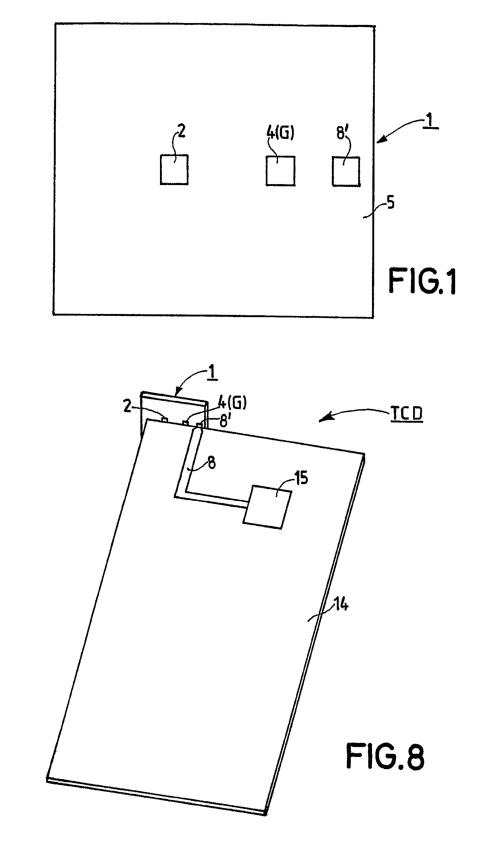
[0038]FIG. 1 shows an embodiment of an antenna configuration 1 having a size of 12×11×1 mm3 and being manufactured by LTCC-technology. The antenna configuration 1 comprises a dielectric substrate 5 said substrate being basically made of a ceramic and contains an antenna structure AS in its interior (not shown in FIG. 1). In more detail the dielectric substrate 5 consists of ten (10) sintered layers of ceramic foils said ceramic foils, in the sintered state, have a dielectric constant of 9.6. The metallization of the track conductors representing the resonant structures (not shown in FIG. 1) consists of a burned silver paste. Only three pads of the antenna configuration 1 are shown in FIG. 1, namely a control electrode 2 and a ground electrode 4 and a feed electrode 8′, said ground electrode 4 being connected to ground G.

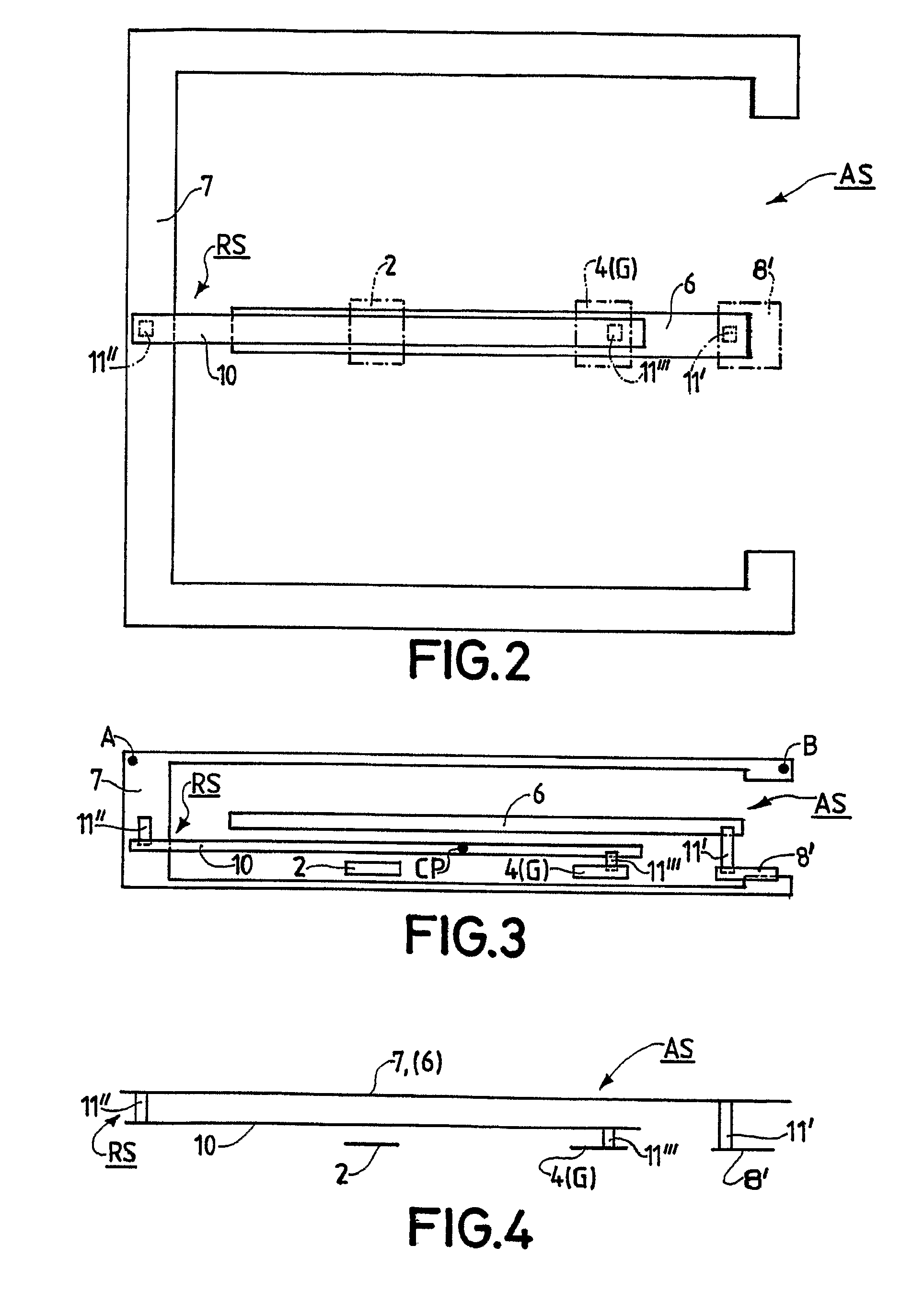
[0039]FIG. 2 shows the antenna structure AS, which is located interior of the antenna configuration 1 according to FIG. 1. The antenna configuration 1 is a dielectri...


PUM


Abstract

Regarding an antenna configuration (1) preferably provided for a telecommunication device and comprising a first resonator structure (6) and second resonator structure (RS) being capacitive coupled with the first resonator structure (6) it is suggested to provide the antenna configuration (1) with a control electrode (2) and a switching stage (3), said control electrode (2) by means of the switching stage (3) being switchably connected to ground (G) and said switching stage (3) enabling to change capacitive coupling of the two resonator structures (6, RS) and thus to change the resonance frequency of the antenna configuration (1) and making possible to switch between a first frequency range and a second frequency range for enhancing the bandwidth and achieving improved matching of the antenna configuration (1).

Description

RELATED APPLICATIONS[0001]This application is a 371 of PCT / IB05 / 50788 filed Mar. 3, 2005, which claims priority under 35 U.S.C. 119 to an application EPO 04101236.0 filed in the Europe on Mar. 25, 2004, the contents of which are incorporated herein by reference.FIELD OF THE INVENTION[0002]The invention relates to an antenna configuration for telecommunication devices, a telecommunication device comprising this antenna configuration, and a method of operating a telecommunication device. Such an antenna configuration being provided for usage in wireless hand-held communication devices such as mobile phones or data communication cards such as memory cards for use in laptops and the like.BACKGROUND OF THE INVENTION[0003]In the area of wireless telecommunication electromagnetic waves in the microwave region are used to transfer information. An essential part of the telecommunication device is thus the antenna configuration, which enables the reception and the transmission of electromagne...

Claims


Application Information

Patent Timeline
Patent Type & Authority Patents(United States)
IPC IPC(8): H01Q3/24H01Q1/22H01Q1/24H01Q1/40H01Q1/42H01Q5/00H01Q5/10H01Q9/04H01Q21/28
CPCH01Q1/22H01Q1/243H01Q1/40H01Q1/42H01Q9/0414H01Q9/0442H01Q9/0457H01Q9/145H01Q21/28
Inventor PELZER, HEIKO
Owner NXP BV
Learn More