
Slit Disk for Modified Faraday Cup Diagnostic for Determing Power Density of Electron and Ion Beams

a technology of modified faraday cup and diagnostic disk, which is applied in the field of determining power density of electron and ion beam, can solve the problems of limiting the number of slits, reducing the accuracy of reconstruction, so as to increase the number of slit angles available, the effect of improving the accuracy of reconstruction

Active Publication Date: 2010-02-11
LAWRENCE LIVERMORE NAT SECURITY LLC
View PDF3 Cites 13 Cited by
  • Summary
  • Abstract
  • Description
  • Claims
  • Application Information

AI Technical Summary

Benefits of technology

[0007]The present invention provides an improved tungsten disk with radial slits for use in an enhanced modified Faraday cup (EMFC) system to determine the power density distribution of an electron or ion beam. A beam diagnostic device has already been developed that can be used to measure the beam properties while it is being scanned in a circle over a tungsten disk with radial slits. A time history of the portions of the beam passing through the slits provides beam profile data that is used in conjunction with data acquisition software and computed tomography software to reconstruct the beam power distribution and important beam distribution parameters. The accuracy of the shape of the reconstruction is dependent on the number of beam profiles, with more slits providing higher resolution. In the current embodiment of the tungsten slit disk, the slits extend radially with the number of equally-spaced angles dependent upon the expected size of the beam and the diameter of the circular deflection. The present invention increases the number of slit angles available on the tungsten disk by using slits with sections with different angles and thus improves the resolution of the beam reconstruction.

Problems solved by technology

This produces a weak point where a section of the brittle tungsten could break off, rendering the disk 102 useless.
However, a number of equipment-specific factors such as working distance from the electron beam gun and deflection coil design limit the maximum deflection circle diameter, thus limiting the number of slits.
Since tungsten is a brittle material, the disk may crack if the slits are too close together and / or any additional forces are put on the disk.
However, this method requires a precision rotation stage inside the vacuum chamber along with additional control electronics.
Some electron beam equipment may not have this capability readily available, so a method of increasing the number of profiles without additional hardware is desired.

Method used


Image

  • Slit Disk for Modified Faraday Cup Diagnostic for Determing Power Density of Electron and Ion Beams
  • Slit Disk for Modified Faraday Cup Diagnostic for Determing Power Density of Electron and Ion Beams
  • Slit Disk for Modified Faraday Cup Diagnostic for Determing Power Density of Electron and Ion Beams

Examples


first embodiment

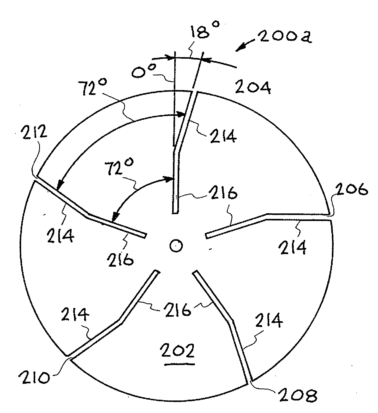
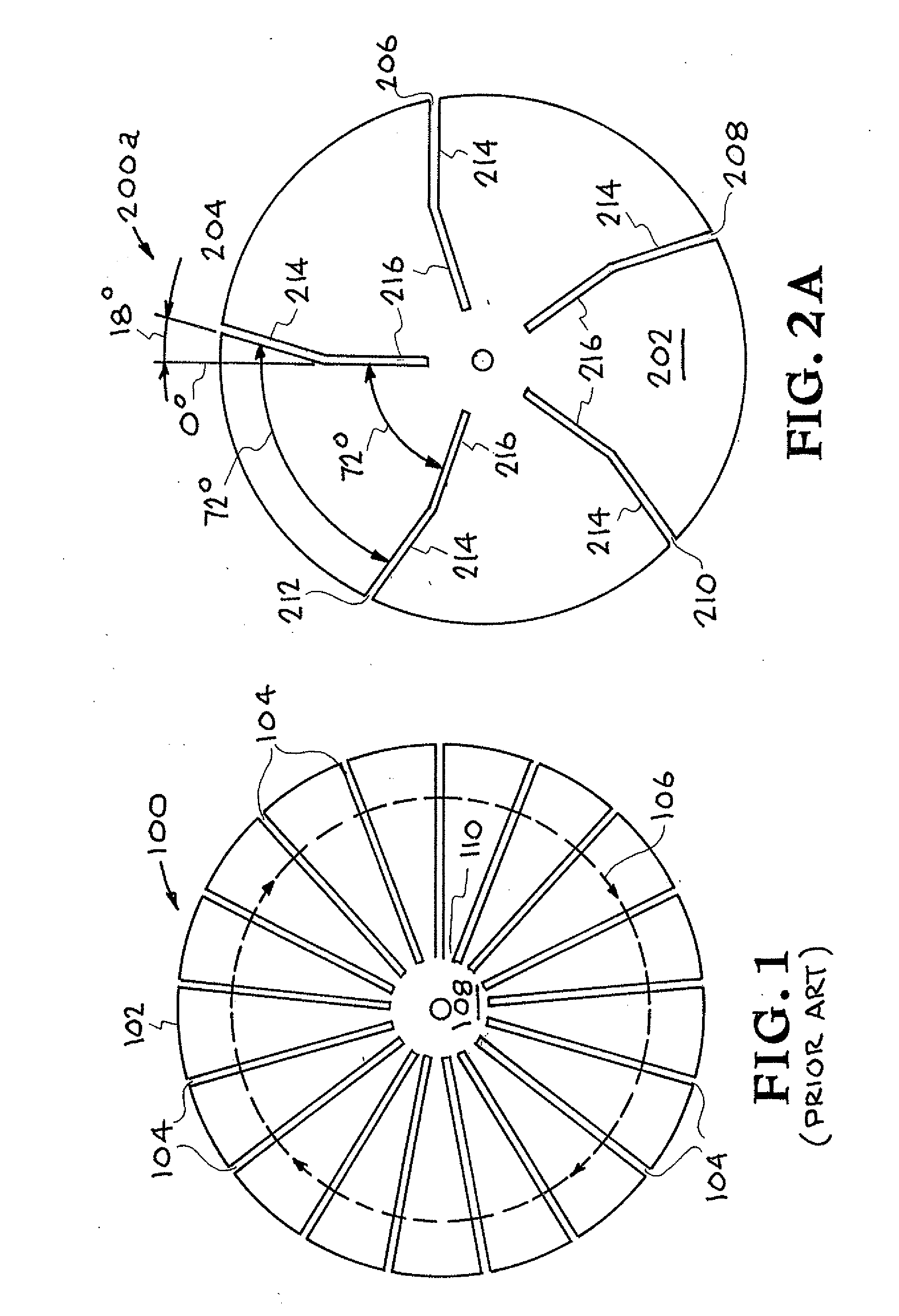
[0031]FIG. 2A shows an improved slit disk system showing a “bent slit” design. The improved slit disk system is designated generally by the reference numeral 200a. For the purposes of this figure the tungsten disk 202 is shown with only five slits (204, 206, 208, 210, and 212 with an angular spacing between them of 72°. However this technique may be extended to any greater odd number of slits that may be manufactured. The “bent slit” provides two angles at which the beam can be scanned compared to the one angle of a straight slit. The angular spacing between slits is determined by dividing 360° by the number of slits. In this case 360° divided by 5 slits provides an angular spacing of 72°. The bent sections 214 of the slits deviate from the radial portions 216 of the slits by ¼ of this angular spacing (18° in this case), thus providing a second set of slits with the same 72° relative to each other but offset 18° from the first set.

second embodiment

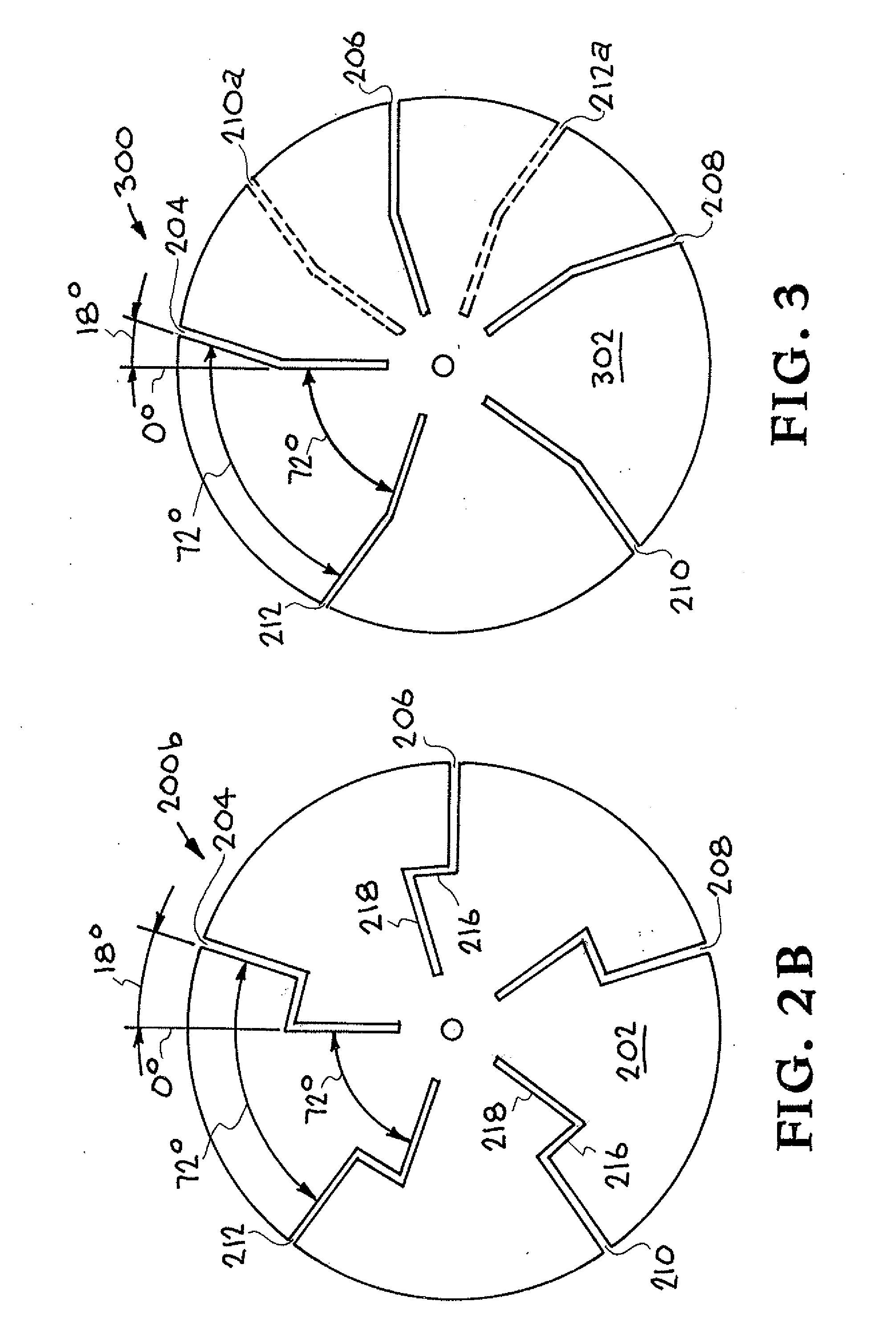
[0032]Referring now to FIG. 2B an improved slit disk showing a “crooked slit” design. This improved slit disk system is designated generally by the reference numeral 200b. FIG. 2B shows a second way of providing multiple angles with a single slit. In this embodiment of the new design, the inner and outer portions of the slit are both positioned radially while being connected by a small transverse section. The outer angle differs from the inner angle by 18° for the same reasons given above for the “bent” configuration.

[0033]For the purposes of this figure the tungsten disk 202 is shown with only five slits (204, 206, 208, 210, and 212 with an angular spacing between them of 72°, however this technique works for any odd number of slits that may be manufactured. As in the “bent slit” design, the “crooked slit” design also provides two angles at which the beam can be scanned compared to the one angle of a straight slit, however the main difference is that in this case both the inner and...


PUM


Abstract

A diagnostic system for characterization of an electron beam or an ion beam includes an electrical conducting disk of refractory material having a circumference, a center, and a Faraday cup assembly positioned to receive the electron beam or ion beam. At least one slit in the disk provides diagnostic characterization of the electron beam or ion beam. The at least one slit is located between the circumference and the center of the disk and includes a radial portion that is in radial alignment with the center and a portion that deviates from radial alignment with the center. The electron beam or ion beam is directed onto the disk and translated to the at least one slit wherein the electron beam or ion beam enters the at least one slit for providing diagnostic characterization of the electron beam or ion beam.

Description

[0001]The United States Government has rights in this invention pursuant to Contract No. DE-AC52-07NA27344 between the United States Department of Energy and Lawrence Livermore National Security, LLC for the operation of Lawrence Livermore National Laboratory.BACKGROUND[0002]1. Field of Endeavor[0003]The present invention relates to electron and ion beams and more particularly to a slit disk for modified faraday cup diagnostic for determining power density of electron and ion beams.[0004]2. State of Technology[0005]Electron beams are considered to be the most precise and clean method available for welding thick sections of materials. Unfortunately, electron beams suffer one critical deficiency, namely the repeatability of focusing the beam to a known power density. Without the ability to reliably reproduce the power distribution in an electron beam, weld quality cannot be guaranteed. This problem is exacerbated by the fact the many welds are made over a period of time and with diffe...

Claims


Application Information

Patent Timeline
Patent Type & Authority Applications(United States)
IPC IPC(8): H01J47/00H01J3/14
CPCH01J2237/24405H01J37/244
Inventor TERUYA, ALAN T.ELMER, JOHN W.PALMER, TODD A.
Owner LAWRENCE LIVERMORE NAT SECURITY LLC
Learn More