Method for molding thermoplastic resin

a thermoplastic resin and thermoplastic resin technology, applied in the field of thermoplastic resin molding methods, can solve the problems of inconvenient cooling, long cycle time, and inconvenient shrinkage ratio during cooling, and achieve the effects of reducing the viscosity of the preform surface, vast improvement of the molding cycle time, and increasing productivity

Inactive Publication Date: 2010-02-11
MUNEKATA TAKATUKI OSAKA JP
View PDF1 Cites 1 Cited by
  • Summary
  • Abstract
  • Description
  • Claims
  • Application Information

AI Technical Summary

Benefits of technology

[0030]In the first and fourth aspects of the present invention, the viscosity of preform surfaces is decreased by dissolving carbon dioxide in the preform surfaces. Therefore, press molding or embossing can be performed under conditions in which a mold is maintained at a predetermined temperature lower than a hardening temperature of a thermoplastic resin. With this, the molding cycle time is vastly improved to increase productivity, compared with conventional methods which require heating the mold before a pressing process and cooling the mold in a cooling process. Furthermore, since the resin temperature is not changed by hardening, a molded product can be obtained without a substantial decrease in dimensional accuracy caused by shrinkage of the resin.
[0031]In the second and fifth aspects of the present invention, since the mold is heated before a pressing process and is cooled in a cooling process, as in the conventional press molding or embossing, the molding cycle time is not largely improved. However, the viscosity of the preform surfaces is largely decreased and transferability of microscopic surface asperities is vastly improved. Furthermore, a vast improvement in birefringence is achieved due to strain relaxation. As described in the third and sixth aspects of the present invention, the degree of decrease in viscosity of the preform surface and the thickness of a layer having the decreased viscosity can be strictly controlled by changing the pressure and temperature of carbon dioxide charged between the mold cavity surface and the preform surface and by changing the contact time of the preform with the carbon dioxide. When molding is performed under conditions where the layer having the decreased viscosity becomes thicker than the preform, the viscosity of the entire preform is decreased to reduce internal strain. Therefore, a molded product having low birefringence can be obtained.

Problems solved by technology

Nowadays, these products are required to have lower birefringence or more fine transferability, but there are limitations in manufacturing such products by conventional injection molding.
However, in these processes, the preform is melted again before a pressing process.
Therefore, preheating of the resin in the mold and a long cycle time are disadvantageously required, though sufficient transferability of microscopic patterns and low birefringence are achieved.
Furthermore, since the preform is repeatedly melted and cooled, the shrinkage ratio during cooling is not constant and the dimensional accuracy decreases.
However, Japanese Unexamined Patent Application Publication No. 10 (1998)-128783 does not relate to press molding and embossing.
Furthermore, since the hardening temperature of the resin is decreased by filling the mold with carbon dioxide, this method cannot be applied to press molding.
However, the preform prepared by the method in Japanese Unexamined Patent Application Publication No. 2002-052583 cannot be applied to press molding and embossing, because of the different molding principle.
Therefore, this method cannot be applied to press molding and embossing.

Method used


Image

  • Method for molding thermoplastic resin
  • Method for molding thermoplastic resin
  • Method for molding thermoplastic resin

Examples


example 1

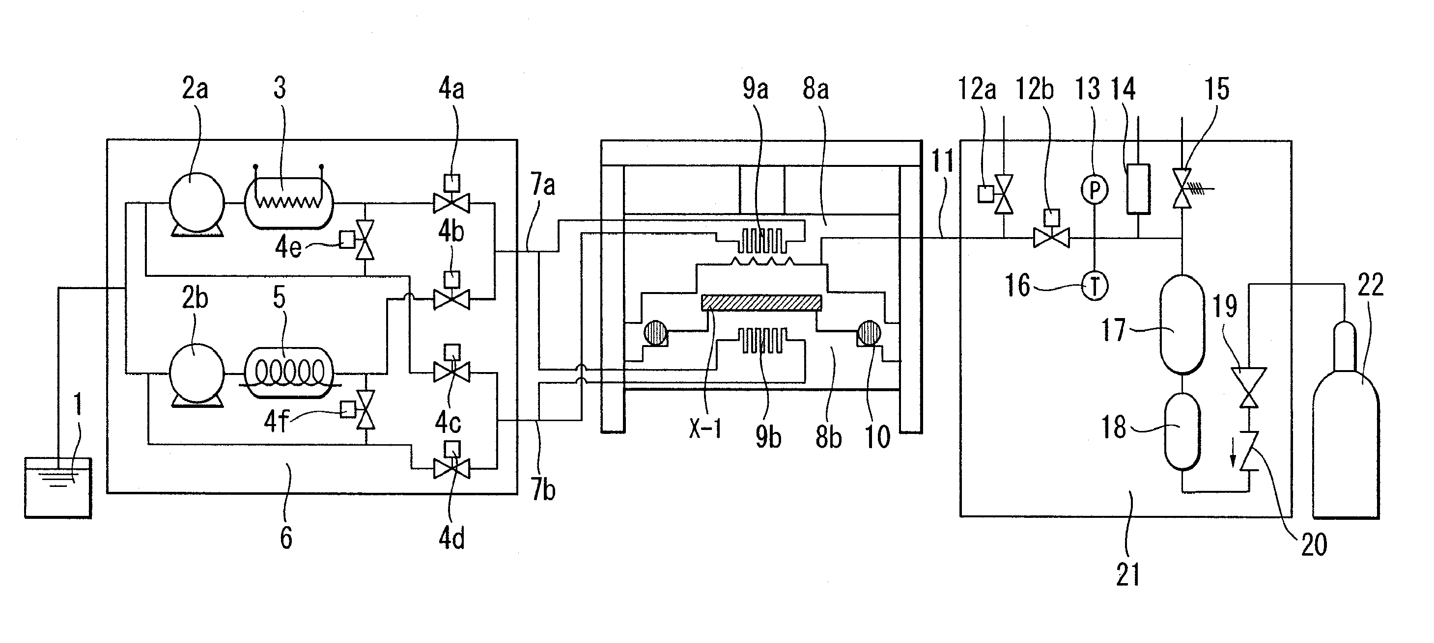
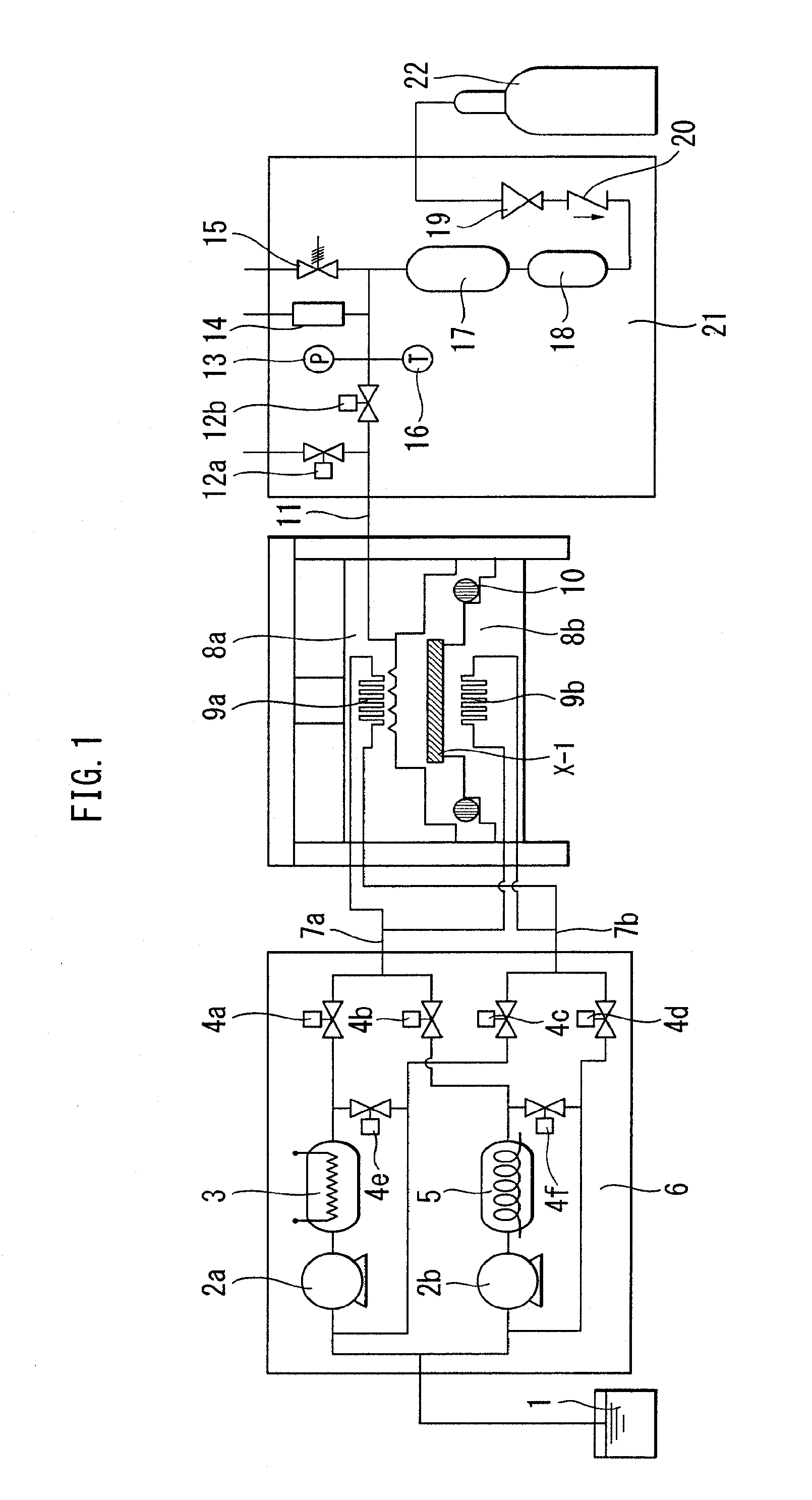
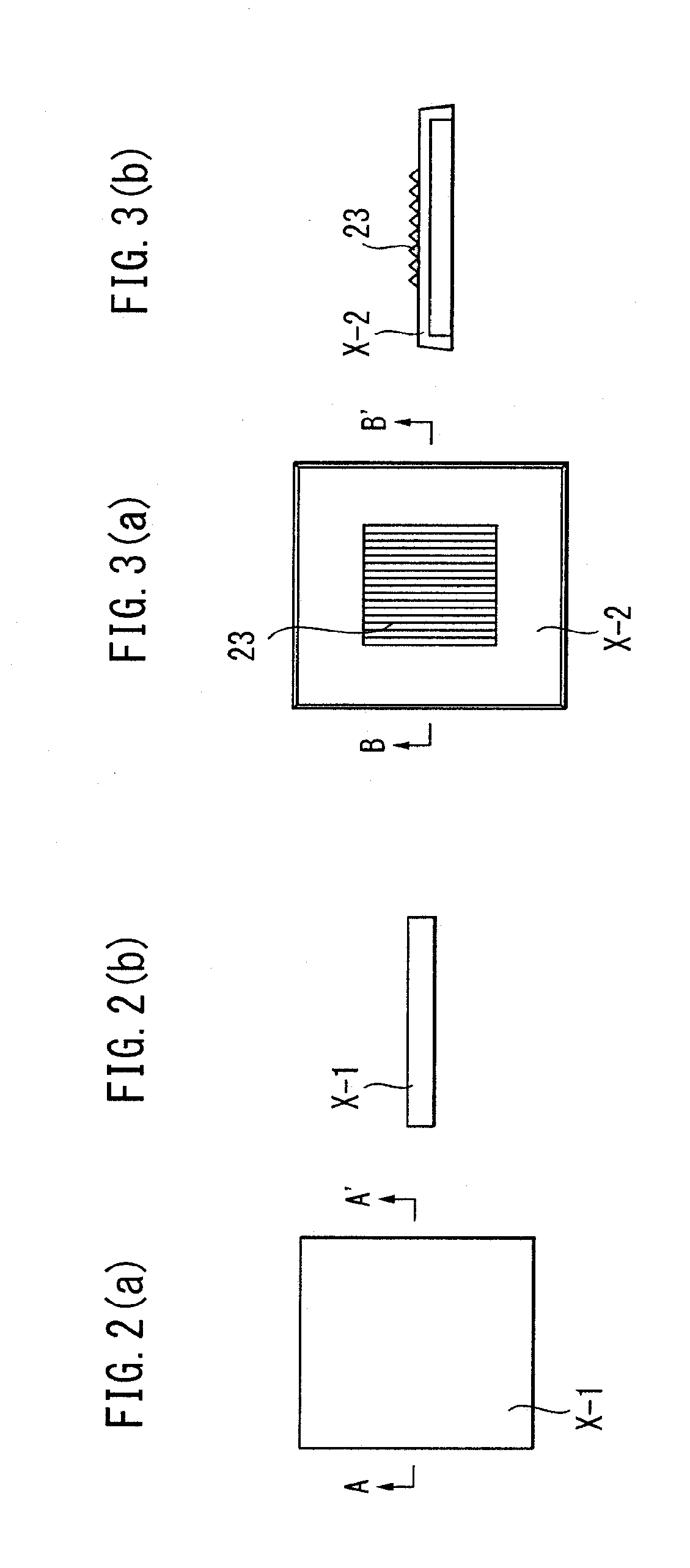
[0046]This example corresponds to the first aspect of the present invention, and will be described in detail with reference to the drawings. FIG. 1 shows the whole molding apparatus. In FIG. 2, (a) is a plan view of a preform X-1, and (b) is a cross sectional view taken along the line A-A′. In FIG. 3, (a) is a plan view of a molded product X-2, and (b) is a cross sectional view taken along the line B-B′. In FIG. 4, (a) shows a molding process, and (b) shows hardening temperature of a resin changing according to the molding process and a mold temperature.

[0047]In the drawings, reference numerals 8a and 8b denote an upper half and a lower half, respectively, of a mold for press molding. The insides of the upper and lower halves 8a and 8b are provided with heat exchangers 9a and 9b, respectively, for heating the mold 8a and 8b by circulating hot water. The lower half 8b is provided with a sealing member 10 for guaranteeing airtightness when the mold 8a and 8b are sealed. Temperature of...

example 2

[0051]Molding was performed as in EXAMPLE 1 except that the charging pressure of carbon dioxide was 15 MPa. Conditions for molding are shown in Table 1, and evaluation of the molded product is shown in Table 2.

example 3

[0052]Molding was performed as in EXAMPLE 1 except that the temperature of carbon dioxide was 60° C. Conditions for molding are shown in Table 1, and evaluation of the molded product is shown in Table 2.


PUM

PropertyMeasurementUnit
hardening temperatureaaaaaaaaaa
widthaaaaaaaaaa
widthaaaaaaaaaa

Abstract

In press molding or embossing a thermoplastic resin for producing a molded product excellent in transferability of microscopic surface asperities and having high quality with high productivity, a preform of a thermoplastic resin is heated to about the hardening temperature of the thermoplastic resin constituting the preform. The preform is embedded between an upper half and a lower half of a mold which are maintained at a temperature of about the hardening temperature of the thermoplastic resin, and then the mold is closed at a low pressure. Carbon dioxide is dissolved in a surface of the preform by charging carbon dioxide between a surface of the mold and the surface of the preform in order to reduce the viscosity of the preform surface. The surface of the mold is brought into contact with the preform having the reduced surface viscosity by increasing a pressing pressure. Then, carbon dioxide is discharged, and a molded product is extracted. Thus, the molded product excellent in transferability of microscopic surface asperities and having high quality can be produced with high productivity.

Description

CROSS REFERENCE TO RELATED APPLICATIONS[0001]This application is a divisional application under 37 CFR 1.53(b) of pending prior application Ser. No. 12 / 401,346 filed Mar. 10, 2009.BACKGROUND OF THE INVENTION[0002]1. Field of the Invention[0003]The present invention relates to methods for molding thermoplastic resins by dissolving resin-soluble gases such as carbon dioxide in surfaces of preforms of thermoplastic resins. More specifically, the present invention relates to methods for molding thermoplastic resins using preforms and molds having restrictive temperature conditions.[0004]2. Description of the Related Art[0005]Products such as optical recording media and light-transmitting substrates have microscopic surface patterns and are required to have high transferability of the surface patterns. Products such as optical lenses for cameras and printers are required to have low birefringence. Conventionally, these products are manufactured by injection molding of thermoplastic resin...

Claims


Application Information

Patent Timeline
Patent Type & Authority Applications(United States)
IPC IPC(8): B29C43/52
CPCB29C43/00B29C43/003B29C43/021B29C43/52B29C2045/1702B29C2043/025B29C2043/3222B29C2043/527B29C2043/566B29C43/56
Inventor OHBA, KAZUYATATEYAMA, HIROFUMITSUCHIYA, ATSUSHI
Owner MUNEKATA TAKATUKI OSAKA JP
Why Eureka
Try Eureka