Organic electroluminescence display including a spacer and method for fabricating the same

a technology of electroluminescence display and spacer, which is applied in the manufacture of electrode systems, electric discharge tubes/lamps, and discharge tubes luminescnet screens, etc., can solve the problems of difficult mounting of fine metal masks on conventional spacers, the material of one pixel's organic eml can invade the regions of other pixels, and the sparse spacing of one pixel

Active Publication Date: 2010-02-11
SAMSUNG DISPLAY CO LTD
View PDF4 Cites 70 Cited by
  • Summary
  • Abstract
  • Description
  • Claims
  • Application Information

AI Technical Summary

Benefits of technology

[0012]In another embodiment, a method of fabricating an organic light emitting device may comprise: providing a substrate; providing a set of spacers having portions that extend in a plurality of directions between pixels, wherein some of the portions are at least long as a side of the pixels; mounting a mask on the set of spacers, wherein the mask defines areas in the pixels that are targeted for organic material; and depositing organic material for the pixels based on the mounted mask, wherein the set of spacers substantially prevents organic material for one of the pixels from invading into another pixel.

Problems solved by technology

The spacers, however, tend to be sparsely spaced among the pixels and tend to have a relatively small area.
Unfortunately, even with the use of the fine metal mask, material for the organic EML of one pixel can invade into the regions of other pixels.
In addition, conventional spacers typically provide a limited support structure and it can be difficult to mount the fine metal mask on conventional spacers.
Fine metal masks often get caught or snagged by the spacer during mounting or transport of the mask.

Method used


Image

  • Organic electroluminescence display including a spacer and method for fabricating the same
  • Organic electroluminescence display including a spacer and method for fabricating the same
  • Organic electroluminescence display including a spacer and method for fabricating the same

Examples


Embodiment Construction

[0019]Some embodiments of the present disclosure will be described below with reference to the accompanying drawings, in which exemplary embodiments of the disclosure are shown. This disclosure may, however, be embodied in different forms and should not be construed as limited to the embodiments set forth herein.

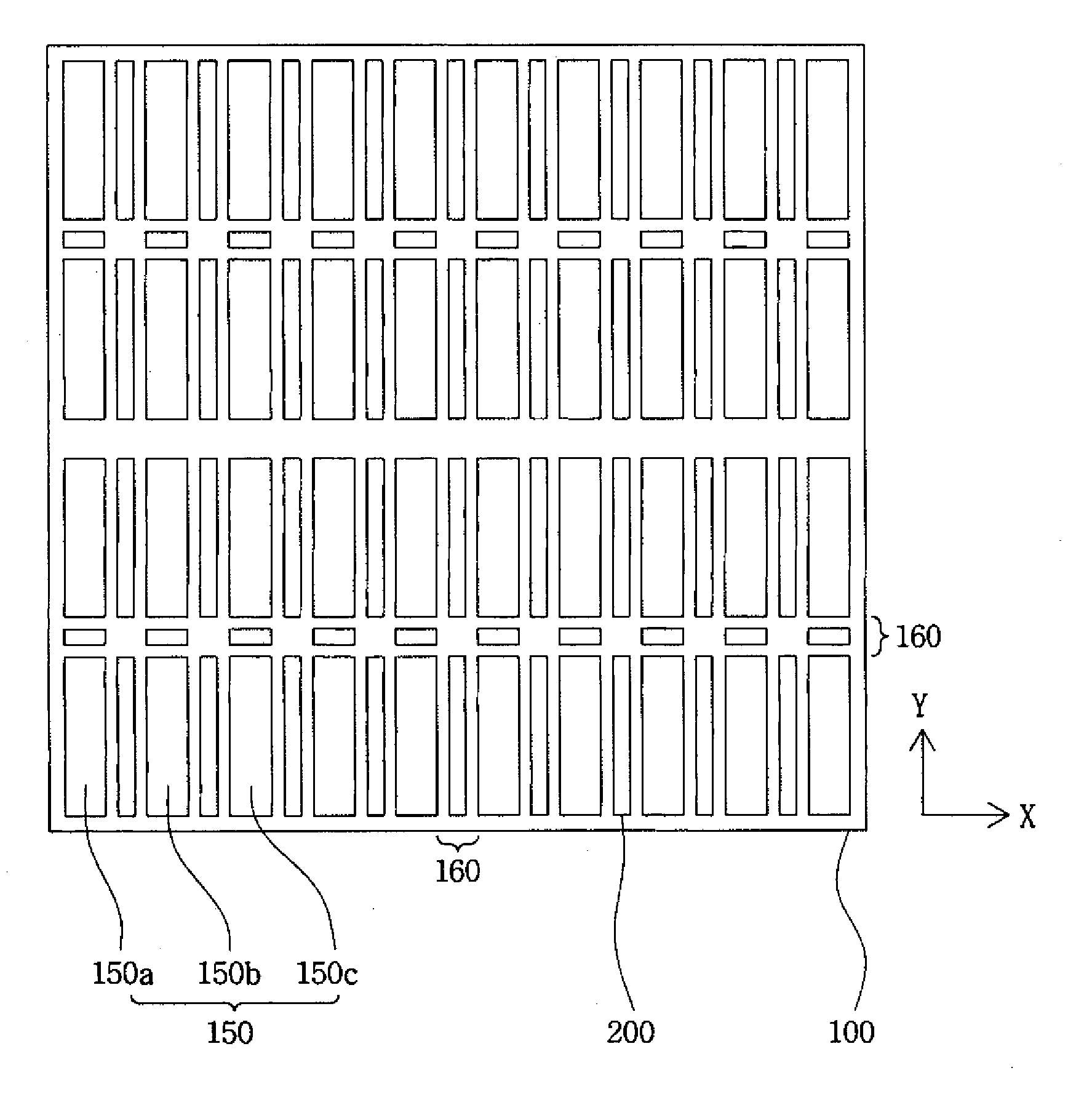
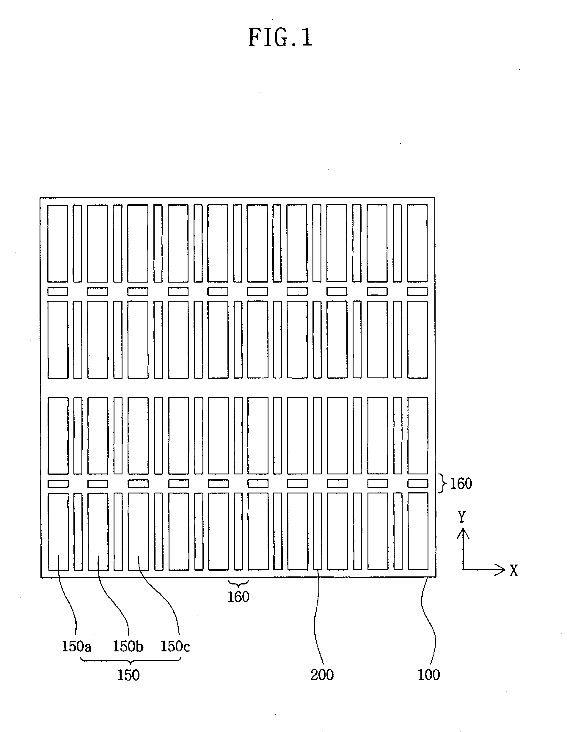
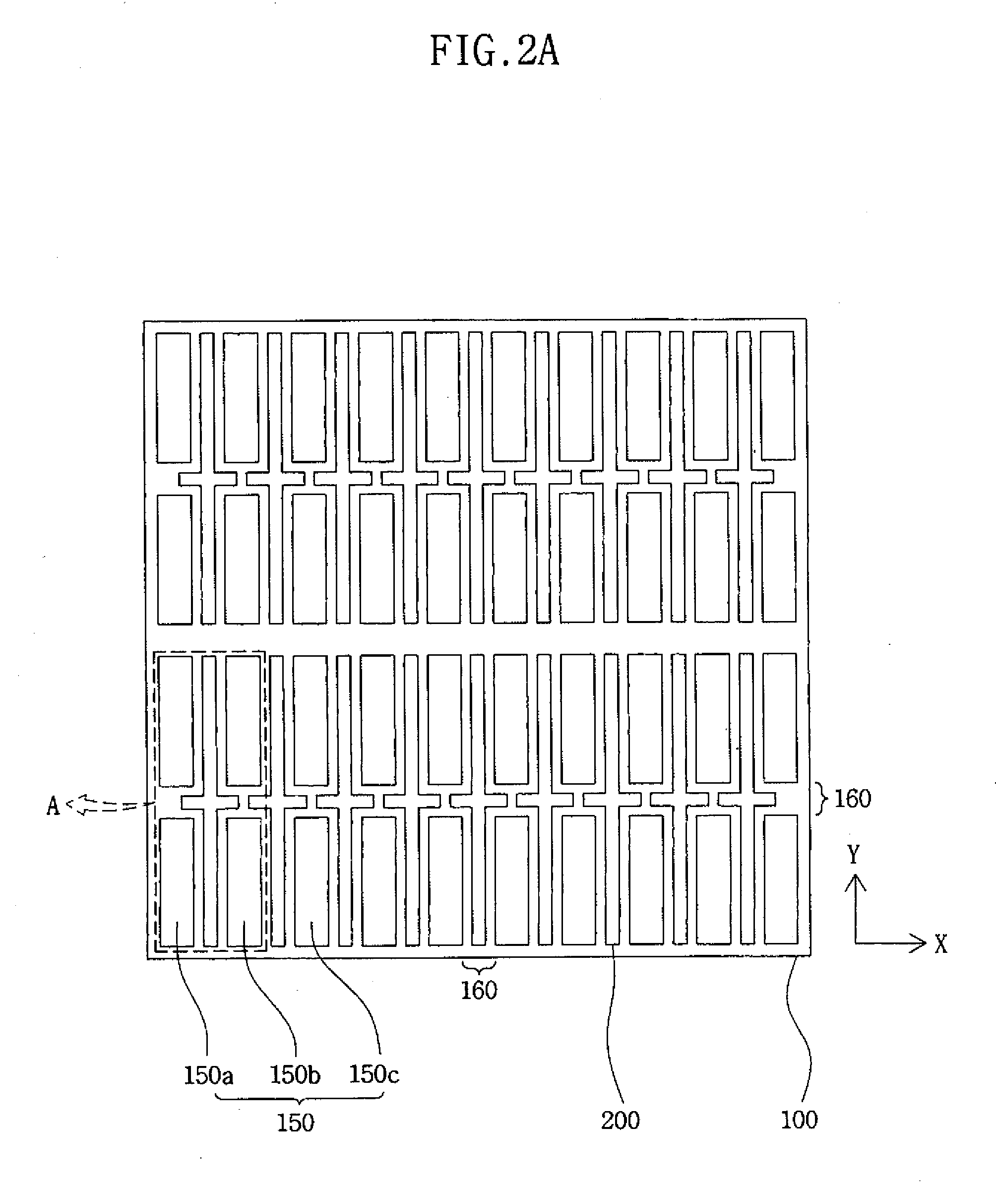
[0020]FIG. 1 illustrates the layout of a pixel region of an organic light emitting diode (OLED) according to an exemplary embodiment of the present disclosure. As shown, a display device may comprise a substrate 100 having various pixel regions 150, non-pixel regions 160, and spacers 200.

[0021]The pixel regions 150 may be pixels of various colors. For example, the pixel regions 150 may include red (R) pixels 150a, green (G) pixels 150b, and blue (B) pixels 150c.

[0022]The pixel regions may be surrounded by non-pixel regions 160, such as, peripheral non-pixel regions around each of the pixels 150a, 150b, and 150c. An insulating layer (not shown) can also be disposed on the no...


PUM


Abstract

Embodiments of the present disclosure provide an organic electroluminescence display device. The display device may include a set of multi-directional spacers that are interposed between the pixels of the display. In one embodiment, the spacers are positioned in both lengthwise and crosswise directions. In another embodiment, the spacers include a first portion that is extends lengthwise between pixels and one or more portions that extend laterally from the first portion between pixels. In yet another embodiment, the spacers include portions that extend in multiple directions between pixels. The spacers may substantially surround each of the pixels and may serve as a boundary, for example, that prevents organic material for one pixel from being incorrectly deposited in another pixel. The spacers can be configured as a support structure, such as, for a metal mask during fabrication of the display device. In addition, the multi-directional aspect of the spacers may be useful in protecting the pixels from damage, such as, when a metal mask is moved during mounting or during fabrication of the display device.

Description

CROSS-REFERENCE TO RELATED APPLICATIONS[0001]This application claims priority to U.S. Provisional Application No. 61 / 077,052, filed on Jun. 30, 2008, and entitled “Organic Electroluminescence Display Including a Spacer and Method for Fabricating the Same,” which is herein incorporated by reference in its entirety.BACKGROUND[0002]1. Field[0003]The present disclosure relates to an organic light emitting diode (OLED) having one or more spacers. More particularly, it relates to an OLED having spacers having dimensions sufficient to prevent organic material intended for a pixel region from leaking or invading into other pixel regions during deposition of the organic material. In addition, the present disclosure may relate to an OLED having spacers that provide an improved mounting structure for a mask used during fabrication of the OLED.[0004]2. Description of the Related Art[0005]An organic light emitting diode (OLED) is a device that includes an organic emission layer (organic EML), wh...

Claims


Application Information

Patent Timeline
Patent Type & Authority Applications(United States)
IPC IPC(8): H01J1/54H01J9/20
CPCH01L51/5012H01L27/3246H10K59/122H10K50/11H01L33/22H10K71/10
Inventor KO, JUNG-WOOLEE, SANG-SHINPARK, SANG-SOOKANG, TAEK-KYOHONG, SEUNG-JU
Owner SAMSUNG DISPLAY CO LTD
Why Eureka
Try Eureka