Charging device and charging system

a charging device and charging system technology, applied in the direction of electric devices, short-circuit testing, engine-driven generator propulsion, etc., can solve the problems of electrical leakage, inability to perform a charging operation smoothly using the foregoing charging device, and interruption of the electrical power supply path, so as to achieve the effect of smoothly performing the charging operation on the electrical devi

Active Publication Date: 2010-02-11
TOYOTA JIDOSHA KK
View PDF5 Cites 57 Cited by
  • Summary
  • Abstract
  • Description
  • Claims
  • Application Information

AI Technical Summary

Benefits of technology

[0009]Thus, according to the present invention, a charging op

Problems solved by technology

However, if the relay has a welded contact, the control circuit cannot cause the electric power supply path to be interrupted after the checking of the operation of the leakage detecting circuit.
In this case, the electrical leakage is likely to remain.
It

Method used


Image

  • Charging device and charging system
  • Charging device and charging system
  • Charging device and charging system

Examples


Embodiment Construction

[0015]The following explains an embodiment of the present invention in detail with reference to figures. Note that the same and equivalent parts in the figures are given the same reference characters, and explanation therefor is not repeated.

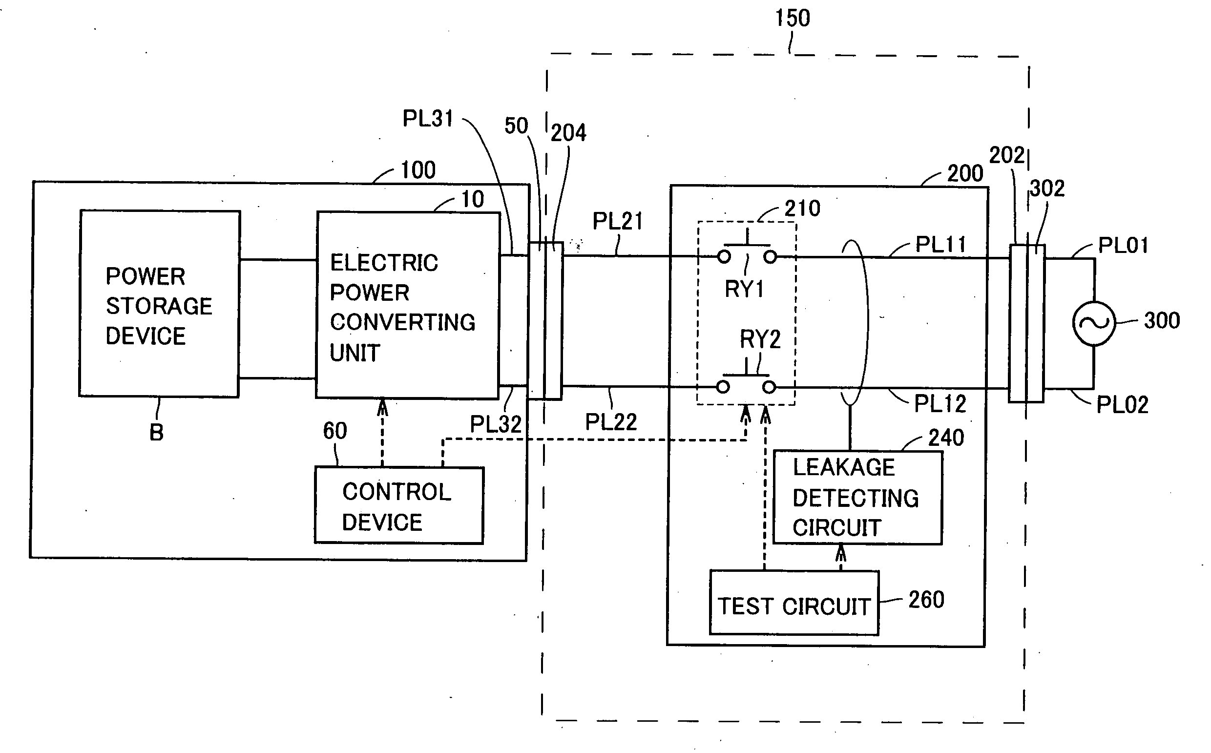
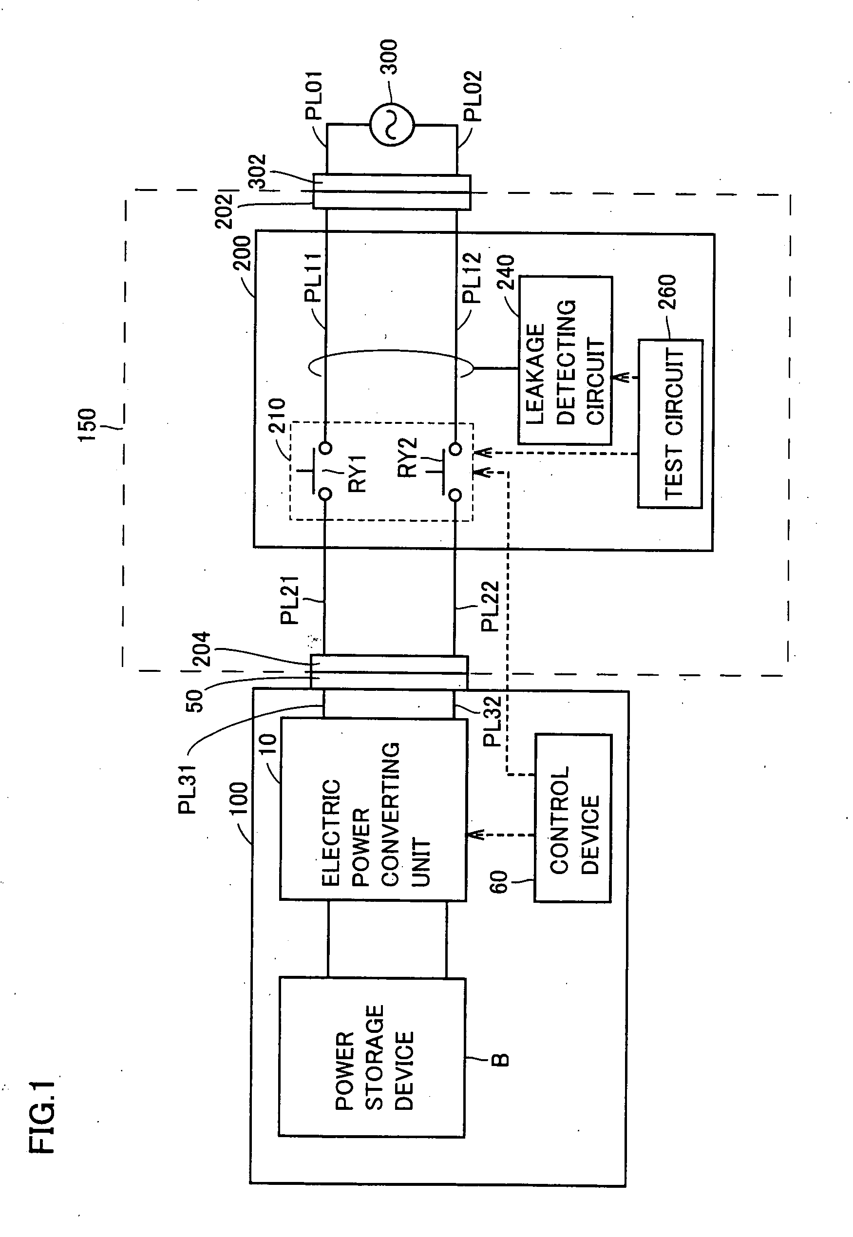
[0016]FIG. 1 illustrates a charging device and a charging system according to the embodiment of the present invention. Referring to FIG. 1, the charging system according to the embodiment of the present invention includes an electrical device 100 configured to be chargeable, and a charging device 150. Charging device 150 is provided between electrical device 100 and an alternate current (ac) electric power source 300 for charging electrical device 100.

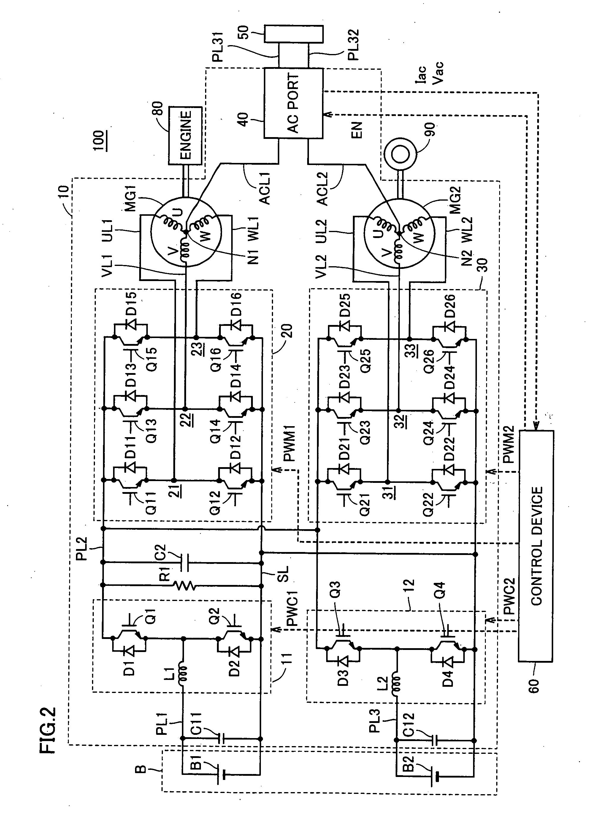
[0017]Electrical device 100 includes an electric power converting unit 10, a power storage device B, a control device 60, and power lines PL31, PL32. Charging device 150 includes connectors 202, 204, power lines PL11, PL12, PL21, PL22, and a charge control device 200.

[0018]Ac electric power source ...


PUM


Abstract

A test circuit first detects whether or not a relay unit is normal, and then examines an operation of leakage detecting circuit. This allows relay unit to interrupt an electric power supply path including power lines more securely if electrical leakage occurs in the electric power supply path. If welding in the contact of the relay unit is detected before starting charging of a power storage device included in an electrical device, a control device does not allow the charging of the power storage device, which can prevent a problem from occurring in the electrical device.

Description

TECHNICAL FIELD[0001]The present invention relates to a charging device and a charging system, particularly, a technique enabling a smooth operation in charging a battery of an electric vehicle using an external electric power source.BACKGROUND ART[0002]Japanese Patent Laying-Open No. 2000-354332 discloses a charging device for an electric vehicle. This charging device includes a relay for opening and closing an electric power supply path from an external electric power source to an electric vehicle; a leakage detecting circuit for detecting electrical leakage based on current flowing through the electric power supply path; a test circuit for intentionally causing electrical leakage at the start of supplying electric power from the external electric power source to an electric power supply circuit; a control circuit for controlling the relay so that the electric power supply path is brought into an open state, when the leakage detecting circuit detects electrical leakage. Prior to c...

Claims


Application Information

Patent Timeline
IPC IPC(8): H02J7/02B60L3/04H02H3/16H02J7/00
CPCB60L3/04Y02T90/127G01R31/025H01M10/441B60L3/0069B60L7/14B60L11/123B60L11/14B60L11/1812B60L11/1814B60L11/1816B60L11/1824B60L11/1864B60L15/007B60L15/2009B60L2210/14B60L2210/40B60L2220/14B60L2220/54B60L2220/56B60L2240/423B60L2240/529B60L2240/547B60L2240/549B60L2240/527Y02T10/7077Y02T10/7005Y02T10/7241Y02T10/7225Y02T10/7061Y02T10/7275Y02T10/6217Y02T10/642Y02T10/641Y02T90/121Y02T90/14G01R31/007B60L50/16B60L50/61B60L53/14B60L53/22B60L53/24B60L58/21G01R31/52Y02E60/10Y02T10/62Y02T10/64Y02T10/70Y02T10/7072Y02T10/72Y02T90/12
Inventor OTAKE, SHINICHI
Owner TOYOTA JIDOSHA KK
Why Eureka
Try Eureka