Spray non-contact cutting type antenna and its fabrication method

Inactive Publication Date: 2010-02-11
AUDEN TECHNO
View PDF0 Cites 15 Cited by
  • Summary
  • Abstract
  • Description
  • Claims
  • Application Information

AI Technical Summary

Benefits of technology

[0015]A device shell having a spray non-contact cutting type antenna made according to the present invention has the antenna be incorporated into the plastic shell without occupying any extra space. When compared with conventional manufacturing techniques, the invention eliminates posterior assembly and thermal fusion / ultrasonic sealing processes, saving much manufacturing time and lowering the defect rate.

Problems solved by technology

Conventionally, the installation of a cell phone antenna in a device shell is complicated.
After cutting the antenna into the desired shape, a series of procedures including posterior assembly and thermal fusion / ultrasonic sealing must be performed, wasting much manufacturing time and having a defect rate.
This method is not applicable to the formation of a conductive pattern on a rigid plastic device shell, therefore it is not suitable for antenna fabrication.

Method used


Image

  • Spray non-contact cutting type antenna and its fabrication method
  • Spray non-contact cutting type antenna and its fabrication method
  • Spray non-contact cutting type antenna and its fabrication method

Examples


Embodiment Construction

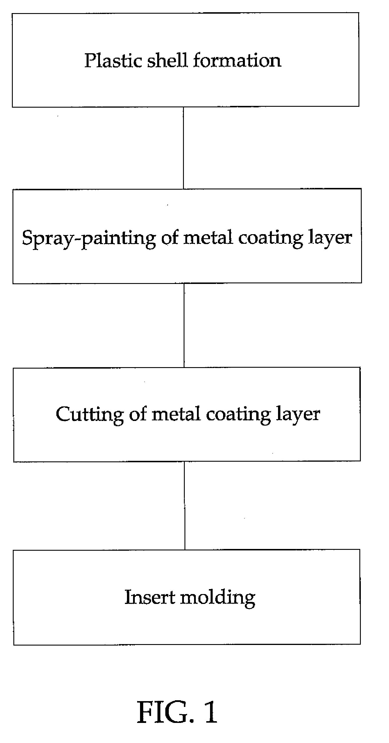
[0023]Referring to FIG. 1 and FIGS. 2˜5, a spray non-contact cutting type antenna fabrication method in accordance with the present invention includes the following four steps:

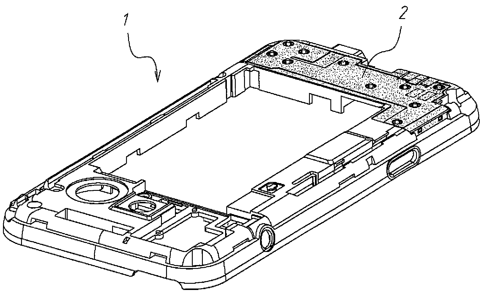
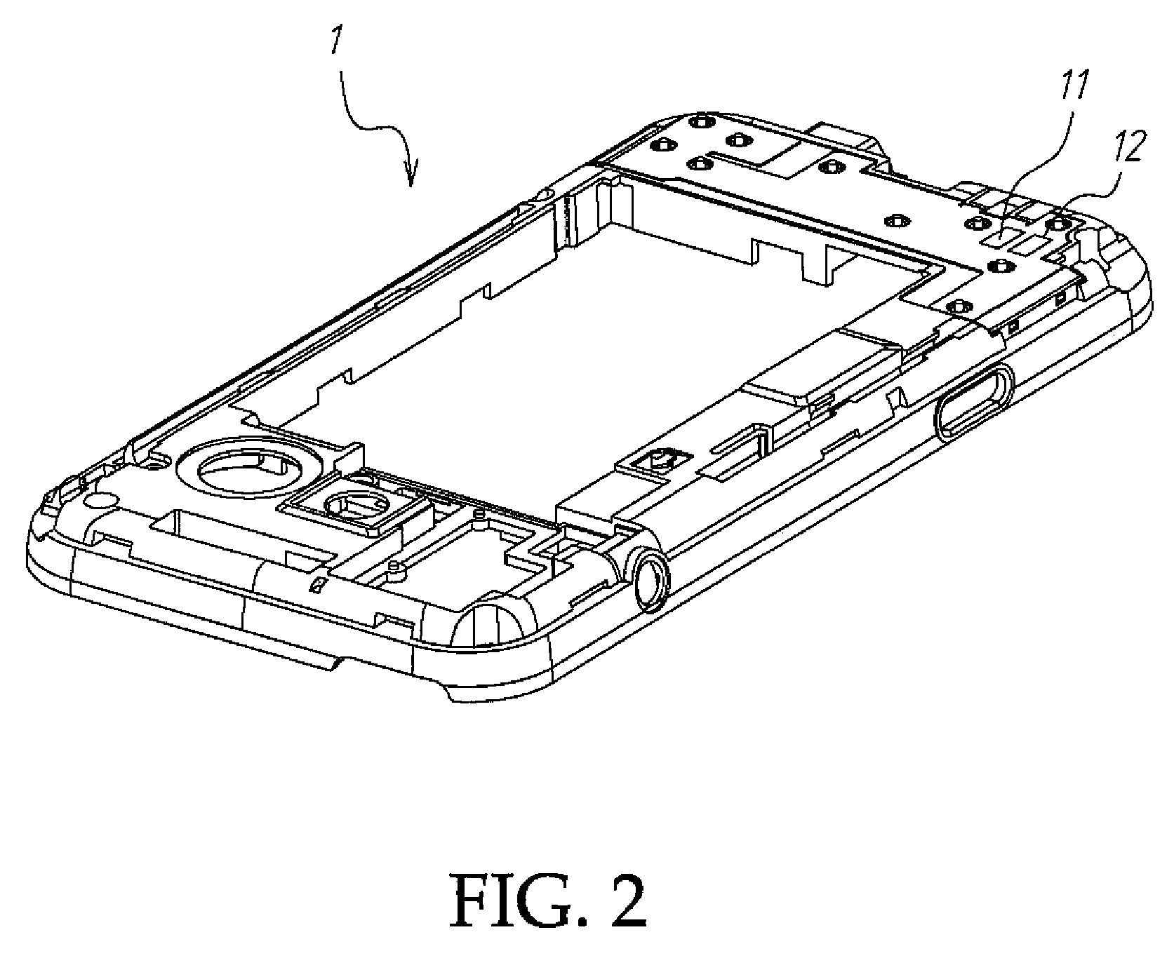
[0024]1. form a plastic shell 1, as shown in FIG. 2;

[0025]2. spray-paint the plastic shell 1 with a metallic spray paint, thereby forming a metal coating layer 2 on the surface of the assigned part of the plastic shell 1, as shown in FIG. 3;

[0026]3. cut the metal coating layer 2 into an antenna 3 subject to a predetermined pattern by means of, for example, a laser engraving technique, as shown in FIG. 4; and

[0027]4. cover the plastic shell 1 with a cover layer 4 by means of using an insert molding or spray painting technique to have the antenna 3 be enveloped in the cover layer 4, as shown in FIG. 5).

[0028]Referring to FIGS. 6 and 7, the plastic shell 1 has a feed-in contact hole 11 and a grounding contact hole 12. When spray-painting the plastic shell 1 with a metallic spray paint to form a metal coating laye...


PUM

PropertyMeasurementUnit
Shapeaaaaaaaaaa

Abstract

A spray non-contact cutting type antenna fabrication method is disclosed to have an antenna radiator be formed on a plastic shell by means of spray-painting a metallic spray paint on the surface of the plastic shell and then cutting the metallic coating into shape, and then to cover the plastic shell with a cover layer by means of an insert molding or spray paining technique to have the antenna radiator be enveloped in the cover layer.

Description

BACKGROUND OF THE INVENTION[0001]1. Field of the Invention[0002]The present invention relates to an antenna fabrication method and more particularly, to a spray non-contact cutting type antenna fabrication method for forming an antenna on a plastic shell by means of spray-painting a metallic spray paint on the plastic shell and then cutting the metallic coating into shape and then covering a cover layer on the plastic shell over the antenna by means of an insert molding technique.[0003]2. Description of the Related Art[0004]Following fast development of wireless communication technology, mobile telephone has become the most important communication tool for most people. From the early mobile telephone designs of big size, exposed antenna, monotonous outer appearance and simple function, modern mobile telephones have light, thin, small and short characteristics with the antenna concealed from sight. Clamshell, slip cover and flip cover mobile telephones are commercially available. Adv...

Claims


Application Information

Patent Timeline
IPC IPC(8): H01Q1/40B28B11/12
CPCB29C45/0053B29C45/14639B29C45/1671B29C2045/0079B29C2045/1673H01Q1/40B29L2031/3437B29L2031/3456H01Q1/243H01Q1/38B29L2031/3431
Inventor CHANG, DANIELCHANG, CHIH-WEI
Owner AUDEN TECHNO
Why Eureka
Try Eureka