Stereoscopic image display and method for producing the same

a technology of stereoscopic image and display layer, which is applied in the manufacture of electrode systems, electric discharge tubes/lamps, instruments, etc., can solve the problems of insufficient crosstalk light blocking of shielding layer with extremely small pattern width, insufficient resolution of display image, and inability to address technique. , to achieve the effect of preventing crosstalk, reducing the pattern width of light shielding layer, and reducing the pattern width

Inactive Publication Date: 2010-02-11
SONY CORP
View PDF67 Cites 29 Cited by
  • Summary
  • Abstract
  • Description
  • Claims
  • Application Information

AI Technical Summary

Benefits of technology

[0014]The above stereoscopic image display has the light-shielding layer on the side of the polarizer opposite the image display panel. In this case, the light-shielding layer is disposed closer to the image display panel than in the case where the light-shielding layer is disposed on the image output side (farther away from the image display panel) of the polarizer, for example, in the case where the light-shielding layer is directly formed on a surface of the retarder. The light-shielding layer...

Problems solved by technology

That is, a light-shielding layer with an extremely small pattern width may insufficiently block crosstalk light.
A light-shielding layer with an extremely large pattern width, however, may decrease the luminance of a displayed image be...

Method used


Image

  • Stereoscopic image display and method for producing the same
  • Stereoscopic image display and method for producing the same
  • Stereoscopic image display and method for producing the same

Examples


Embodiment Construction

[0030]An embodiment of the present invention will now be described. The description will be presented in the following order:

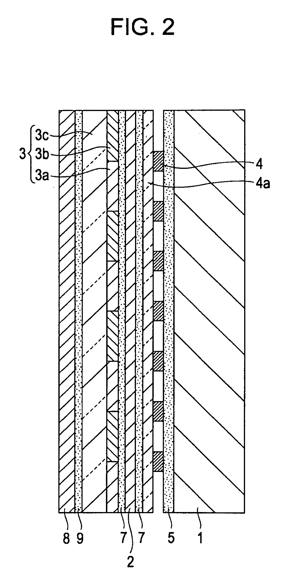
[0031]1. Exemplary structures of stereoscopic image display (first and second exemplary structures)

[0032]2. Method for producing stereoscopic image display (annealing step, light-shielding-layer providing step, positioning step, and bonding step)

[0033]3. Advantages of embodiment

1. Exemplary Structures of Stereoscopic Image Display

[0034]First, exemplary structures of a stereoscopic image display according to this embodiment will be described.

1-1. First Exemplary Structure

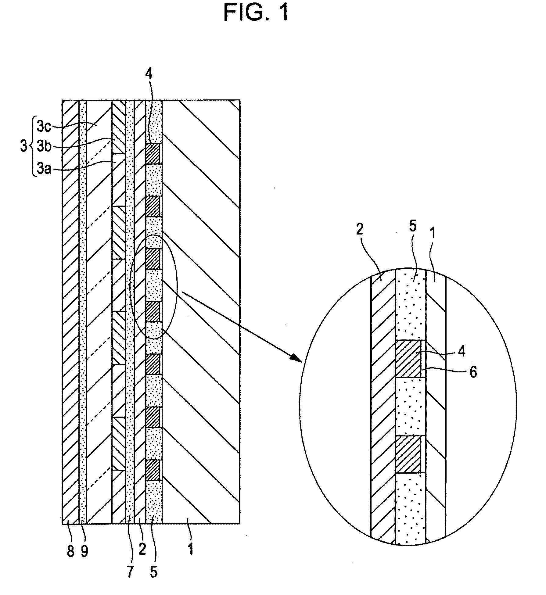
[0035]FIG. 1 is a schematic diagram of a first exemplary structure of the stereoscopic image display according to this embodiment.

[0036]The stereoscopic image display shown includes an image display panel 1, a polarizer 2, a retarder 3, a light-shielding layer 4, a first bonding agent layer 5, air layers 6, a second bonding agent layer 7, an antireflection film 8, and a third bonding agent laye...


PUM


Abstract

A stereoscopic image display includes an image display panel that displays right-eye images and left-eye images in a regularly mixed pattern in a plane; a retarder disposed on an image output side of the image display panel and including right-eye-image display portions, corresponding to the right-eye images, and left-eye-image display portions, corresponding to the left-eye images, that cause polarization so that the right-eye images and the left-eye images have different polarization states; a polarizer disposed between the image display panel and the retarder; and a light-shielding layer disposed between the image display panel and the polarizer so as to correspond to regions including boundaries between the right-eye-image display portions and the left-eye-image display portions of the retarder.

Description

CROSS-REFERENCE TO RELATED APPLICATION[0001]The present application claims priority from Japanese Patent Application No. JP 2008-193102 filed in the Japanese Patent Office on Jul. 28, 2008, Japanese Patent Application No. JP 2008-285022 filed in the Japanese Patent Office on Nov. 6, 2008, Japanese Patent Application No. JP 2008-285021, filed in the Japanese Patent Office on Nov. 6, 2008 and Japanese Patent Application No. JP 2009-105887 filed in the Japanese Patent Office on Apr. 24, 2009, the entire contents of which are incorporated herein by reference.BACKGROUND OF THE INVENTION[0002]1. Field of the Invention[0003]The present invention relates to stereoscopic image displays that display stereoscopic images using right-eye images and left-eye images and methods for producing such stereoscopic image displays.[0004]2. Description of the Related Art[0005]An example of a stereoscopic image display for displaying a stereoscopic image is shown in FIG. 14 (see, for example, Japanese Unex...

Claims


Application Information

Patent Timeline
IPC IPC(8): H04N13/04H01J9/00
CPCG02B27/26G02F2413/09G02F1/133512G02B30/25G02F1/133631
Inventor ABE, HIROMICHIOHNO, HIROSHINIYOMURA, HIDEOKARASAWA, JOJIHORIE, OSAMUOKADA, MASAMICHISAKATA, ATSUSHIKOBAYASHI, TAKAYUKISUTO, TAKANOBU
Owner SONY CORP
Why Eureka
Try Eureka