Discharge lamp lighting device and image display apparatus

a technology of lighting device and discharge lamp, which is applied in the direction of instruments, light sources, projectors, etc., can solve the problems of undesirable lamp voltage vla, sometimes rising lamp voltage vla,

Inactive Publication Date: 2010-02-11
PANASONIC CORP
View PDF10 Cites 30 Cited by
  • Summary
  • Abstract
  • Description
  • Claims
  • Application Information

AI Technical Summary

Problems solved by technology

When the discharge lamp lighting device starts to light the lamp, however, the lamp voltage Vla sometimes rises to a large extent because no consideration is given to the status of the electrodes of the lamp in the previous stable lighting mode.
The phenomenon in which the lamp voltage Vla becomes higher is undesirable.

Method used


Image

  • Discharge lamp lighting device and image display apparatus
  • Discharge lamp lighting device and image display apparatus
  • Discharge lamp lighting device and image display apparatus

Examples


embodiment 1

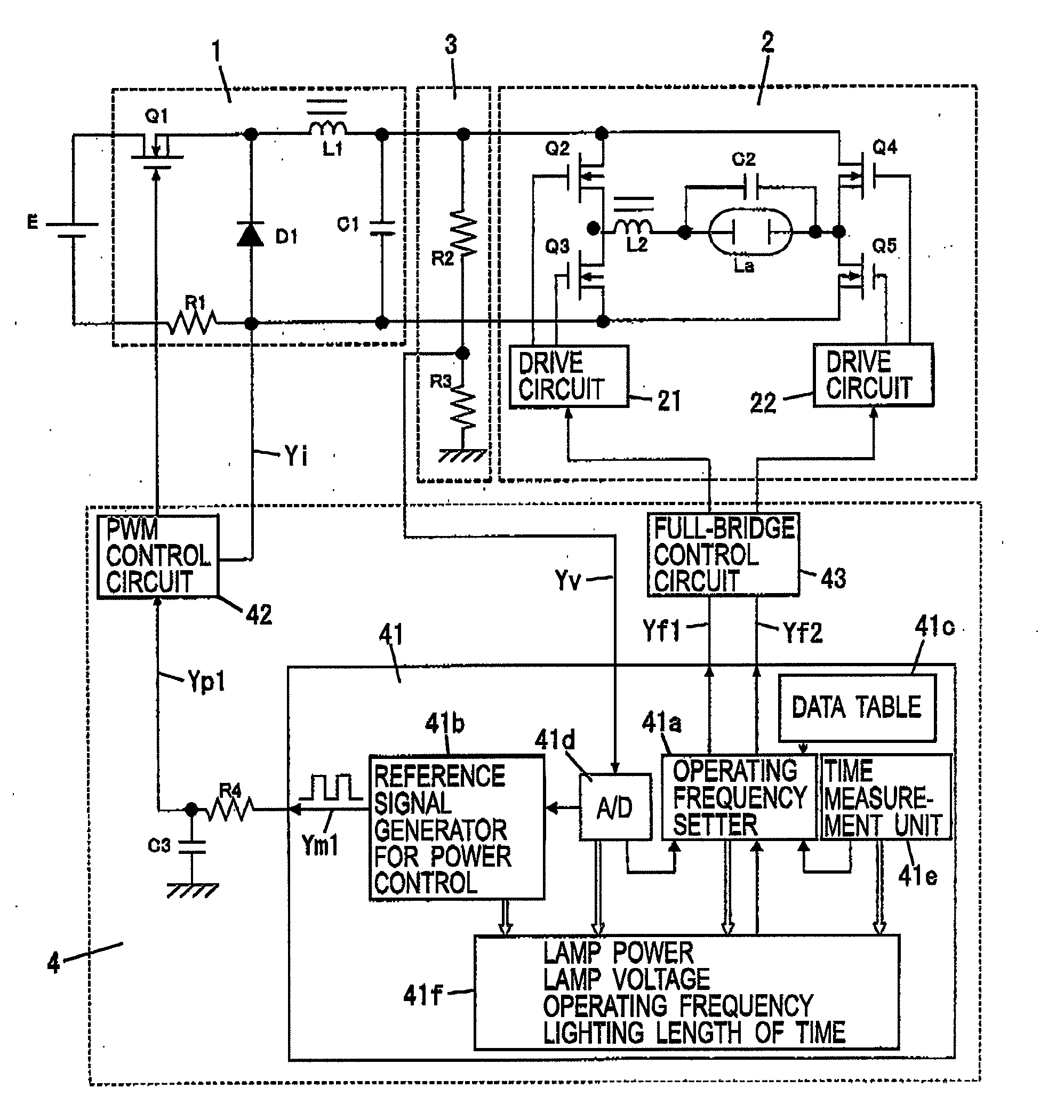
[0035]FIG. 1 shows a circuit diagram of a discharge lamp lighting device according to the present embodiment. The discharge lamp lighting device includes a power converting circuit configured by including: a step-down chopper circuit 1 using a direct-current power supply E as its power source; and a polarity inversion circuit 2 configured to convert a direct-current voltage outputted from the step-down chopper circuit 1, to a rectangular-wave alternating voltage, and thus to apply the rectangular-wave alternating voltage to a discharge lamp La. The discharge lamp lighting device further includes: a lamp voltage detection circuit 3 configured to detect a lamp voltage Vla of the discharge lamp La; and a control circuit 4 configured to control the on and off of each of switching elements Q1 to Q5 provided in the power converting circuit.

[0036]In the step-down chopper circuit 1, the positive electrode of the direct-current power supply E is connected to the positive electrode of the cap...

embodiment 2

[0076]FIG. 8 shows a circuit configuration of a discharge lamp lighting device according to the present embodiment. The micon 41 includes an operating frequency setter 41a, a reference signal generator 41b for power control, a data table 41c, an A / D converter 41d, a time measurement unit 41e, and a memory 41f. The A / D converter 41d is configured to convert a lamp voltage detection signal Yv from the lamp voltage detection circuit 3 to a digital signal, and thus to output the digital signal to the reference signal generator 41b for power control, and the memory 41f.

[0077]The operating frequency setter 41a determines switching frequencies (operating frequencies) of the respective switching elements Q2 to Q5 in a polarity inversion circuit 2. Thus, the operating frequency setter 41a outputs the inverter control signals Yf1, Yf2 corresponding to the determined switching frequencies, to a full-bridge control circuit 43. The full-bridge control circuit 43 controls the drive circuits 21, ...

embodiment 3

[0103]FIG. 15 shows a circuit configuration of a discharge lamp lighting device according to the present embodiment. The micon 41 includes an operating frequency setter 41a, a reference signal generator 41b for power control, a data table 41c, an A / D converter 41d, a time measurement unit 41e, and a memory 41f. The A / D converter 41d is configured to convert a lamp voltage detection signal Yv from the lamp voltage detection circuit 3 to a digital signal, and thus to output the digital signal to the operating frequency setter 41a, the reference signal generator 41b for power control, and the memory 41f.

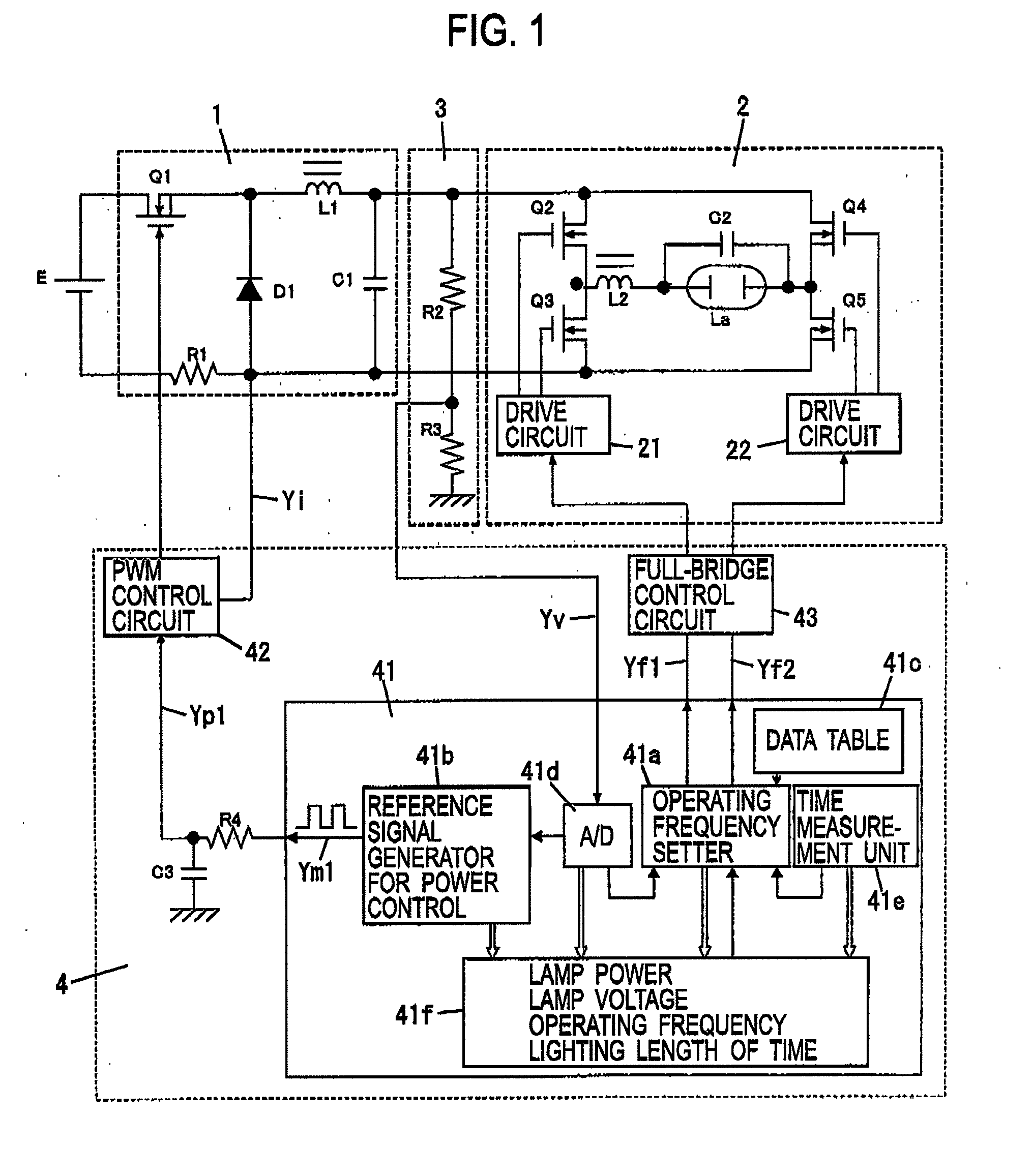
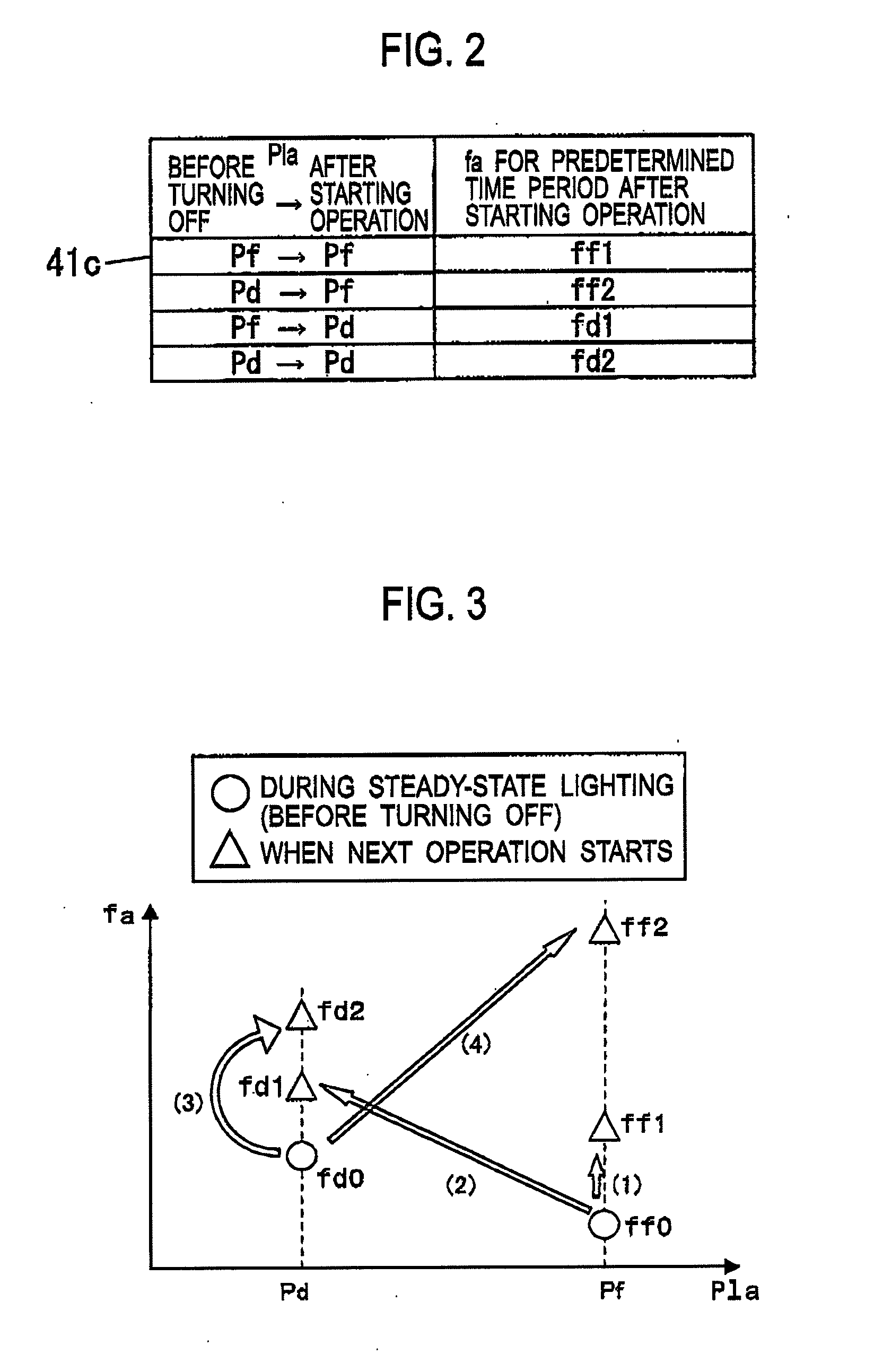
[0104]The operating frequency setter 41a determines switching frequencies (operating frequencies) of the respective switching elements Q2 to Q5 in the polarity inversion circuit 2 on the basis of the lamp voltage detection signal Yv, sets of data which are stored in the data table 41c and the memory 41f, and the time measured by the time measurement unit 41e. Thus, the operating freque...


PUM


Abstract

A discharge lamp lighting device includes: a power converting circuit including a step-down chopper circuit (1) and a polarity inversion circuit (2) configured to convert an output from the step-down chopper circuit (1) to a rectangular-wave alternating-current voltage, and thus to apply the rectangular-wave alternating-current voltage to a discharge lamp (La); and a memory (41f) configured to store a history of an output from the power converting circuit in a previous stable lighting mode. A control circuit (4) controls the on and off of each of switching elements (Q1 to Q5) in the step-down chopper circuit (1) and the polarity inversion circuit (2), and thereby changes the output from the power converting circuit in a predetermined time period after the lamp starts lighting until reaching a stable lighting state on the basis of the history stored in the memory (41f), so that a rise of a lamp voltage Vla is suppressed. This enables extension of the lifespan of the lamp and suppression of the occurrence of arc jump.

Description

TECHNICAL FIELD[0001]The present invention relates to a discharge lamp lighting device and an image display apparatus using the same.[0002]There are discharge lamp lighting devices configured to light high-intensity high-pressure discharge lamps employed in image display apparatuses such as projectors and rear-projection television sets. In recent years, in some of such discharge lamp lighting devices, the operating frequency of the lamp is made variable (see Patent Documents 1 and 2, for example), or the electric current of the lamp is made variable (see Patent Document 3 and 4, for example), as control after the device starts lighting, for the purpose of suppressing arc jump, raising the light emission amount quickly, and extending the lifespan of the lamp.[0003]Parts (a) to (C) of FIG. 25 show a control of an output to the lamp generally implemented after the lamp starts lighting until reaching a stable lighting state. Until the lamp voltage Vla reaches a predetermined voltage, a...

Claims


Application Information

Patent Timeline
Patent Type & Authority Applications(United States)
IPC IPC(8): H05B41/36G03B21/14
CPCH05B41/3925H05B41/2928
Inventor WATANABE, KOJIKONISHI, HIROFUMI
Owner PANASONIC CORP
Why Eureka
Try Eureka