
Pattern Model Positioning Method In Image Processing, Image Processing Apparatus, Image Processing Program, and Computer Readable Recording Medium

Active Publication Date: 2010-02-11
KEYENCE
View PDF3 Cites 51 Cited by
  • Summary
  • Abstract
  • Description
  • Claims
  • Application Information

AI Technical Summary

Benefits of technology

[0013]The present invention was made in order to solve the conventional problems as thus described. A principal object of the present invention is to provide a pattern model positioning method in image processing, an image processing apparatus, an image processing program, and a computer readable recording medium, which can perform fine positioning with higher accuracy at higher speed.
[0014]In order to achieve the above object, a first pattern model positioning method in image processing of, upon searching out of an image to be searched and positioning an object to be searched that is similar to a pre-registered image by use of a pattern model corresponding to the registered image, positioning with accuracy higher than at an initially given position, the method is capable of including the steps of extracting a contour from the registered image; constructing a pattern model of the registered image, in which a plurality of reference points are set on the extracted contour, and also a corresponding point search line having a predetermined length and passing through each reference point as well as being substantially orthogonal to the contour is also allocated to each reference point; acquiring an image to be searched, and also arranging the pattern model so as to be superimposed on the image to be searched in accordance with an initial position included in the image to be searched and corresponding to the registered image; finding a corresponding edge point on the image to be searched corresponding to a reference point of each corresponding point search line of the pattern model out of each pixel in the image to be searched that is positioned as superimposed on the corresponding point search line upon superimposing the pattern model on the initial position on the image to be searched; and taking a distance between each corresponding edge point and a contour including the reference point corresponding to the corresponding edge point as an evaluation value, and performing fine positioning with accuracy higher than accuracy in the given initial position such that an absolute value of an accumulated value of the evaluation values becomes minimal. Thereby, it is possible to use data on the corresponding point search line as the pattern model for fine positioning. Particularly, by using not only the edge strength of the image along but also the edge angle thereof, it is possible to add a direction component, so as to perform highly accurate positioning resistant to a noise component. Further, by changing the length of the corresponding point search line, it is possible to obtain an advantage of being capable of readily changing a corresponding-edge-point search range, so as to adjust the positioning accuracy.
[0015]According to a second pattern model positioning method in image processing, the step of extracting the contour from the registered image can include the steps of extracting a plurality of edge points from the registered image; coupling adjacent edge points among the extracted plurality of edge points, to create a continuous chain; and creating a segment by respectively approximating one or more chains by means of a line and / or a circular arc, and regarding aggregation of the segments as a contour. Thereby, it is possible to construct a pattern model made up of segments approximated by a line and / or a circular arc, so as to realize positioning with higher accuracy.

Problems solved by technology

However, such a conventional region-based search based on image thickness or the like has the problem of being susceptible to a change in illumination upon image pickup, and the like.
However, high accuracy cannot be expected in this technique because whether or not the corresponding point is present on the seek-line is determined based only upon the relation between a size of a differential value and its threshold and an edge direction and an angle component are not considered.
Further, there has been a drawback with this technique in that processing cannot be performed in a case where a plurality of points as candidates of the corresponding point are present on the seek-line, e.g., a double line cannot be processed.
Moreover, in this method, although positioning of a simple shape such as a rectangle and a circle can be realized, positioning of a general and multipurpose shape such as a more complicated shape and a character pattern cannot be performed.
Furthermore, there has been a problem in that accurate edge detection cannot be performed on a thin-linear object to be searched due to the long kernel of the edge detection.
There has consequently been a drawback in that, when a work itself is long and narrow, edge data becomes relatively weak, to be regarded as a noise component, and hence accurate edge detection cannot be expected.
However, there has been a problem with this technique in that, since the corresponding relation between the segment and the point depends only upon the distance therebetween, a point may be computed as the corresponding point even in an inherently non-corresponding relation with the segment in view of the edge direction or the like.
Further, there has also been a problem in that, from necessity of acquiring imaginary points in the image to be searched, the edge detection needs to be performed on every point in a high resolution image as an object to be searched, and hence round-robin processing is performed, leading to an increase in processing time with increase in resolution of the image data.

Method used


Image

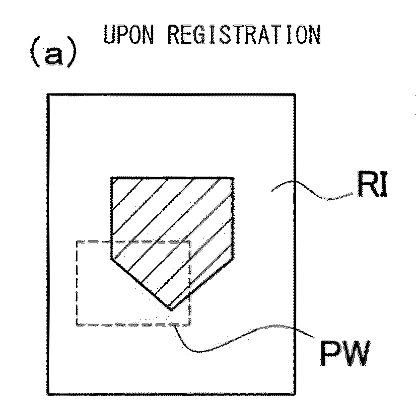
  • Pattern Model Positioning Method In Image Processing, Image Processing Apparatus, Image Processing Program, and Computer Readable Recording Medium
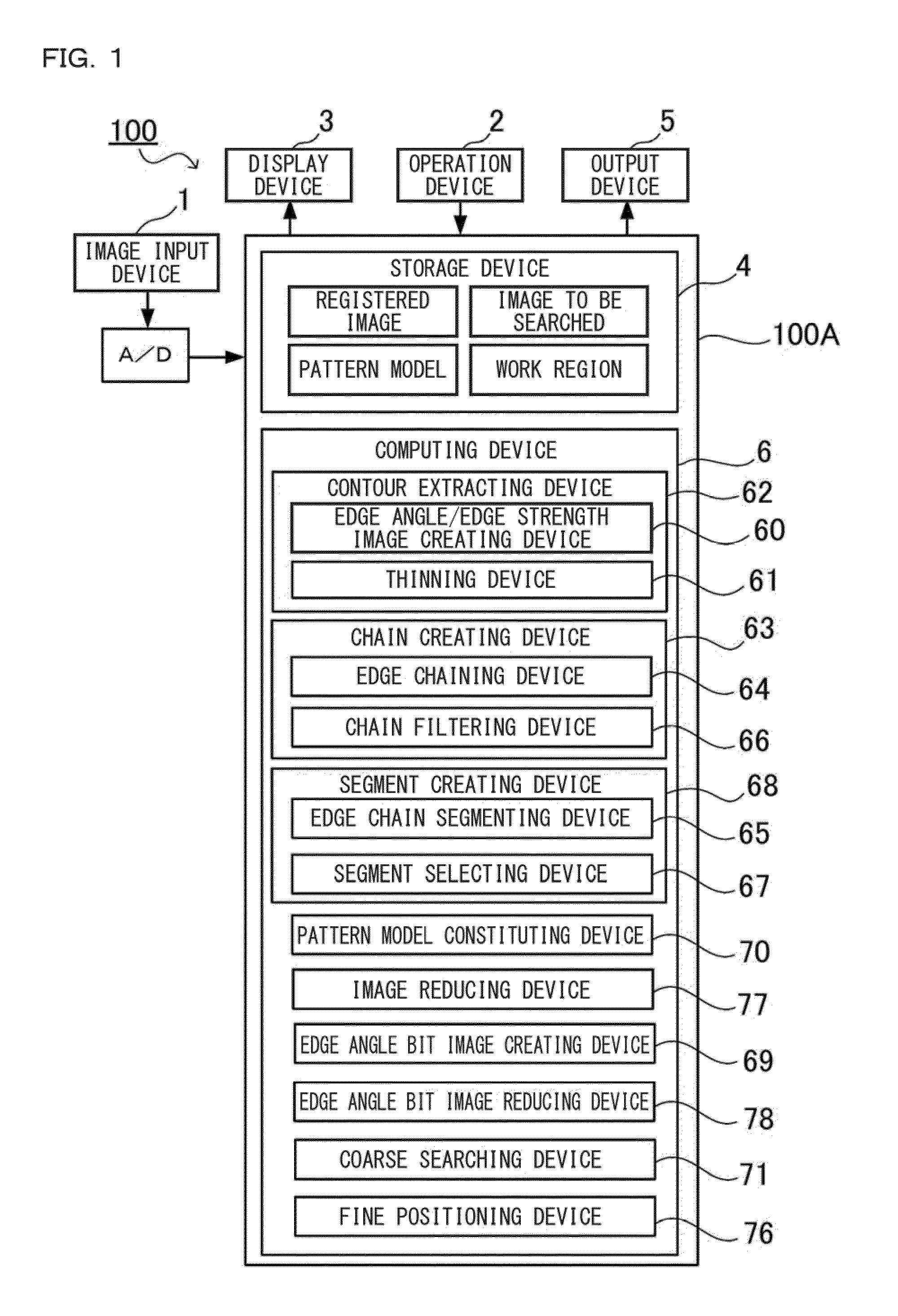
  • Pattern Model Positioning Method In Image Processing, Image Processing Apparatus, Image Processing Program, and Computer Readable Recording Medium
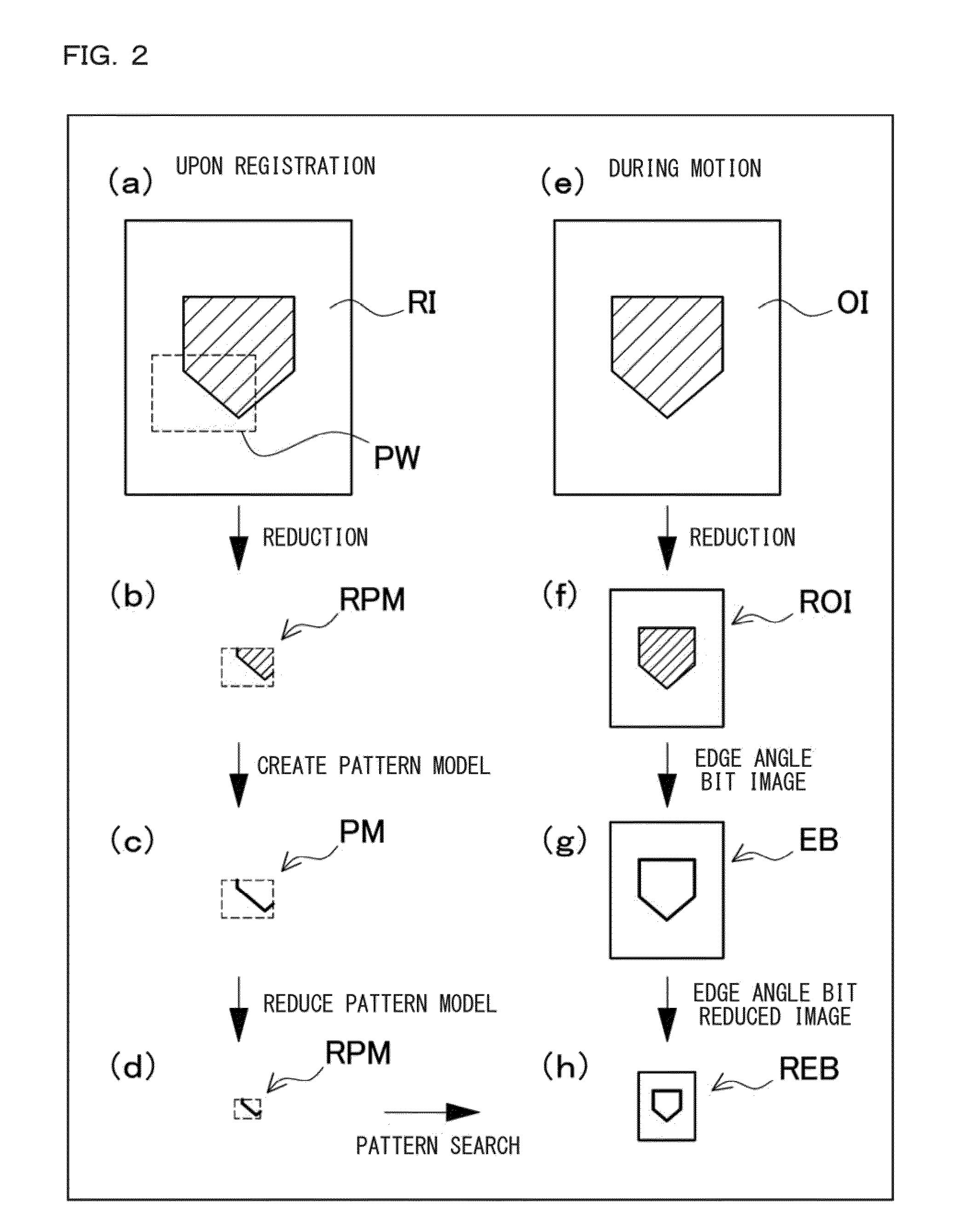
  • Pattern Model Positioning Method In Image Processing, Image Processing Apparatus, Image Processing Program, and Computer Readable Recording Medium

Examples


Embodiment Construction

[0162]In the following, an embodiment of the present invention is described based on drawings. However, the embodiments shown below exemplifies a pattern model positioning method in image processing, an image processing apparatus, an image processing program, and a computer readable recording medium for making a technical concept of the present invention concrete, and the present invention does not specify its pattern model positioning method in image processing, image processing apparatus, image processing program, and computer readable recording medium to the following. Further, the present specification by no means specifies a member shown in the claims to a member in the embodiment. Especially a size, a material, a shape, a relative arrangement and the like of a constitutional component described in the embodiment are not intended on restricting the range of the present invention to those but simply are explanatory examples so long as a specific description is not particularly g...


PUM


Abstract

There is provided a matching method, capable of positioning with higher accuracy at higher speed. The method includes the steps of: constructing a pattern model of a registered image in which a plurality of reference points are set on an extracted contour and a corresponding point search line having a predetermined length and passing through each reference point; acquiring an image and acquiring an initial position corresponding to the registered image to arrange the corresponding point search line of the pattern model; finding a corresponding point on the image corresponding to each reference point with regard to each corresponding point search line at a position along the corresponding point search line on the image; and regarding a relation between each reference point and the corresponding point as an evaluation value and performing fine positioning such that an accumulated value of the evaluation values becomes minimal or maximal.

Description

CROSS-REFERENCE TO RELATED APPLICATIONS[0001]The present application claims foreign priority based on Japanese Patent Applications No. 2008-206478, filed Aug. 9, 2008, and No. 2008-267979, filed Oct. 16, 2008, the contents of which is incorporated herein by reference.BACKGROUND OF THE INVENTION[0002]1. Field of the Invention[0003]The present invention relates to a pattern model positioning method in image processing, an image processing apparatus, an image processing program, and a computer readable recording medium, for performing fine positioning with higher accuracy upon searching out of an image to be searched and positioning a pattern model corresponding to a pre-registered image.[0004]2. Description of the Related Art[0005]An image processing apparatus for processing an image picked up by an image pickup element typically includes: an image pickup apparatus for picking up an image processing object (hereinafter also referred to as “work”); an image data storing device for stor...

Claims


Application Information

Patent Timeline
IPC IPC(8): G06K9/32
CPCG06K9/6202G06T2207/30164G06T2207/20016G06T7/0046G06T7/75G06V10/751
Inventor KIDO, MANABU
Owner KEYENCE
Learn More