
System for generating energy from sea waves

a technology of energy generation system and sea waves, applied in sea energy generation, water power plants, tidal streams/damless hydropower, etc., can solve problems such as complicated energy production process

Inactive Publication Date: 2010-02-11
TAGANSKY ELAZAR
View PDF14 Cites 7 Cited by
  • Summary
  • Abstract
  • Description
  • Claims
  • Application Information

AI Technical Summary

Benefits of technology

[0006]According to the present invention, whereby the captured waves create and build a watercourse above the surface of the sea, exploitation of the flow from the artificial watercourse back to the sea makes the energy production more simple and according to the state of the art.
[0012]Using the present invention, it is possible to raise the water flowing inside the channel to a level higher than that reached by the waves in the respective area. The channel has one or more openings to allow the water to flow back to the sea. The water flowing back to the sea in a continuous current exerts pressure on a water wheel or a turbine or any other technical means which utilizes pressure to generate energy.

Problems solved by technology

However, these methods were characterized by a fundamental disadvantage: Lack of homogenous continuity between one wave and the next, thus considerably complicating the process of energy production.

Method used


Image

  • System for generating energy from sea waves
  • System for generating energy from sea waves
  • System for generating energy from sea waves

Examples


Embodiment Construction

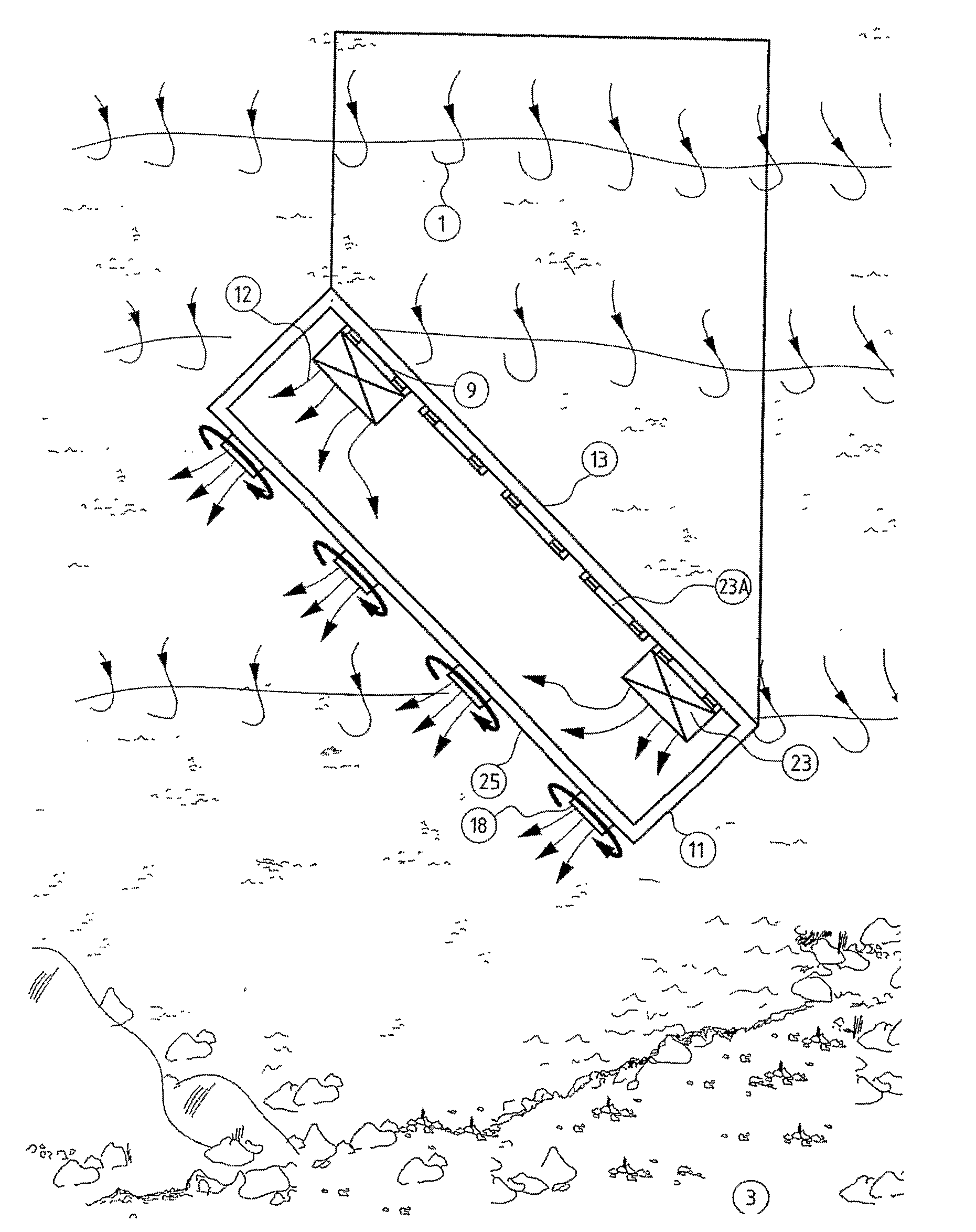
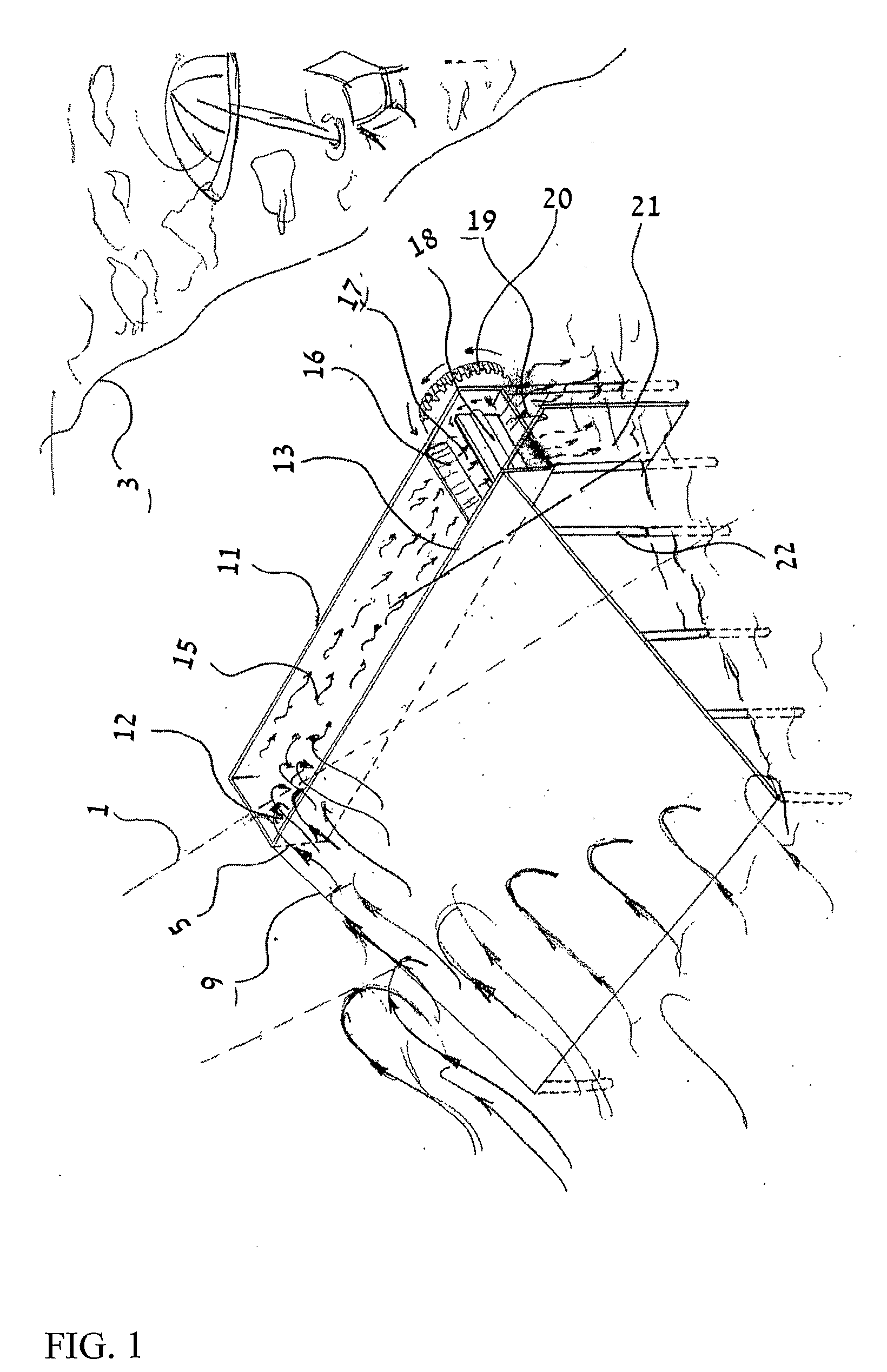
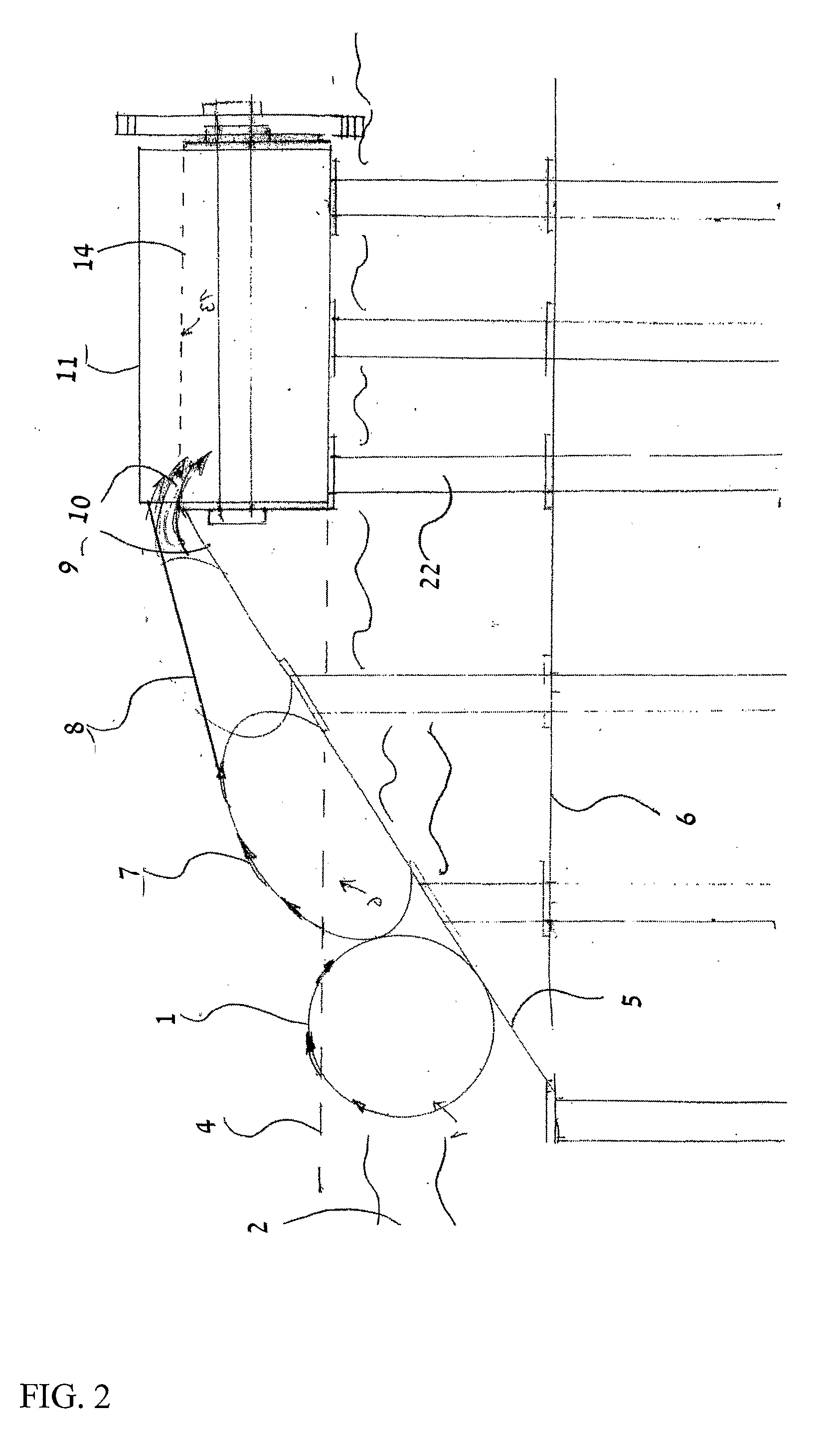
[0024]A preferred embodiment of the present invention will now be described by way of example and with reference to the accompanying drawings.

[0025]Referring to FIGS. 1, 2 and 3, a wave 1 coming from the sea 2 in the direction of the shore 3 in its theoretically round shape and in its major part below sea level 4, hits a slanting structure 5 (slanting in a vertical plane) creating an almost ideal breakwater for capturing the water coming in the wave 1.

[0026]In a preferred embodiment, the slanting structure 5 is located in the depth of the sea, approximately at a point where the wave 1 meets the shore 6 in its natural course, which is at the bottom of the sea 2 flowing in the direction of the shore 3.

[0027]Wave 1, upon encountering the almost ideal slanting structure 5, turns, on contact with the structure 5, from a round shape (an about circular flow of water in a vertical plane) into a generally elliptical shape (an about elliptical flow of water in a vertical plane), as the wave c...


PUM


Abstract

A system for generating energy from sea or ocean waves flowing toward a shore, comprises a channel or a container and a slanting structure constructed above the surface of the sea. The slanting structure is located in the way of waves toward the channel or container so the waves are lifted along the slanting structure wherein the wave energy is transformed into a generally homogenous flow. The water flow enters the channel or container to fill it to a level higher than sea level. Preferably, the slanting structure is placed in a location where the horizontal distance between adjacent waves is twice the depth (vertical distance) between the adjacent waves.

Description

FIELD OF THE INVENTION[0001]The invention relates to a system for generating energy from sea or ocean waves flowing toward a shore.BACKGROUND OF THE INVENTION[0002]The present application claims priority from the patent application filed in Israel by the present applicant, application No. 180052 filed on 14 Dec. 2006, and additions to the above application filed on 28 Oct. 2007.[0003]The present invention relates to a system, whereby sea waves are captured and transformed into a current flowing in a channel constructed above the surface of the sea, generating energy by a continuous and homogenous flow of water on its way back to the sea.[0004]The creation of energy from sea waves has been known in the past. Up to the present, the creation of energy from the sea or ocean waves has been based on the exploitation of these waves in their direct natural form, according to a wide variety of methods. However, these methods were characterized by a fundamental disadvantage: Lack of homogenou...

Claims


Application Information

Patent Timeline
IPC IPC(8): E02B9/08
CPCY02E10/28E02B9/08Y02E10/30Y02E10/20
Inventor TAGANSKY, ELAZAR
Owner TAGANSKY ELAZAR
Learn More