Card edge connector with idc wire termination

a technology of idc wire termination and connector, which is applied in the direction of coupling device connection, coupling/insulating contact member penetrating/cutting insulation/cable strand, etc., can solve the problems of limited idc technology on printed circuit boards, pivotable wire stuffers are difficult to operate without damaging other components, etc., to reduce the overall cost of manufacture, add flexibility, and always be at a premium on the board

Inactive Publication Date: 2010-02-11
TE CONNECTIVITY CORP
View PDF30 Cites 7 Cited by
  • Summary
  • Abstract
  • Description
  • Claims
  • Application Information

AI Technical Summary

Benefits of technology

[0012]This type of connector assembly allows the connector assembly to be built according to the needs of the end user. As electrical connectors can be mounted together to form any length connector assembly, only one type and size of electrical connector needs to be tooled and manufactured. This modular aspect of the connector assembly adds flexibility while reducing the overall cost of manufacture. The use of card edge connectors that utilize insulation displacement termination methods is also advantageous. As board space is always at a premium, the ability to terminate wires to a connector mounted at the edge of a circuit board has significant cost savings, as a smaller board can be used without effecting the operation of the components. In addition, the use of dual slotted insulation displacement terminals further enhances the flexibility of the connector assembly, as various wiring schemes can be effectively and cost efficiently utilized.

Problems solved by technology

While IDCs are very useful, IDC technology has been limited on printed circuit board for use with connectors that employ traditional through hole mount or surface mount technology.
In a typical configuration with the IDC assembled on a circuit board, the pivotable wire stuffers tend to be difficult to operate without damaging other components, particularly when the circuit board has closely spaced components due to space requirements.

Method used


Image

  • Card edge connector with idc wire termination
  • Card edge connector with idc wire termination
  • Card edge connector with idc wire termination

Examples


Embodiment Construction

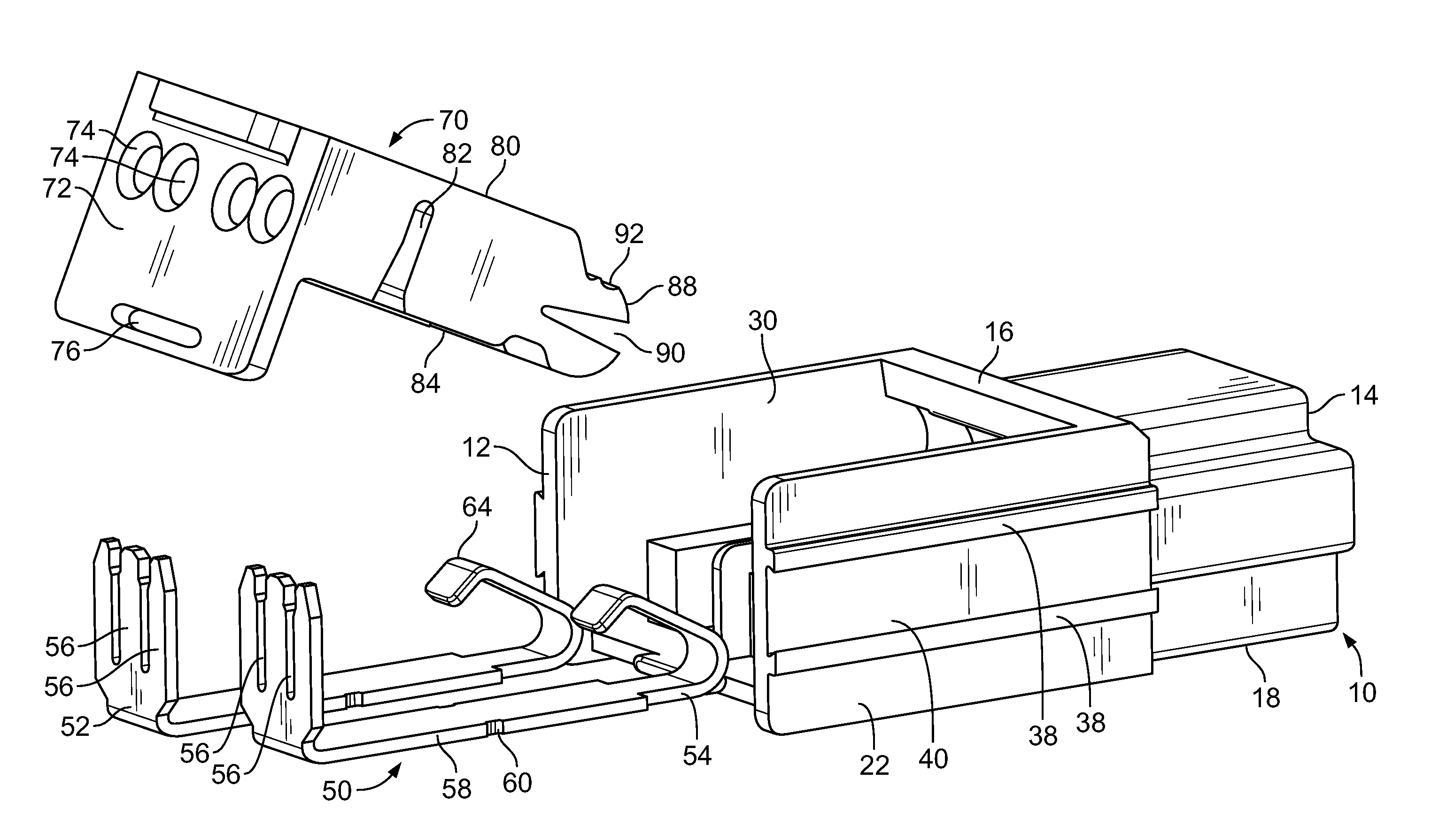
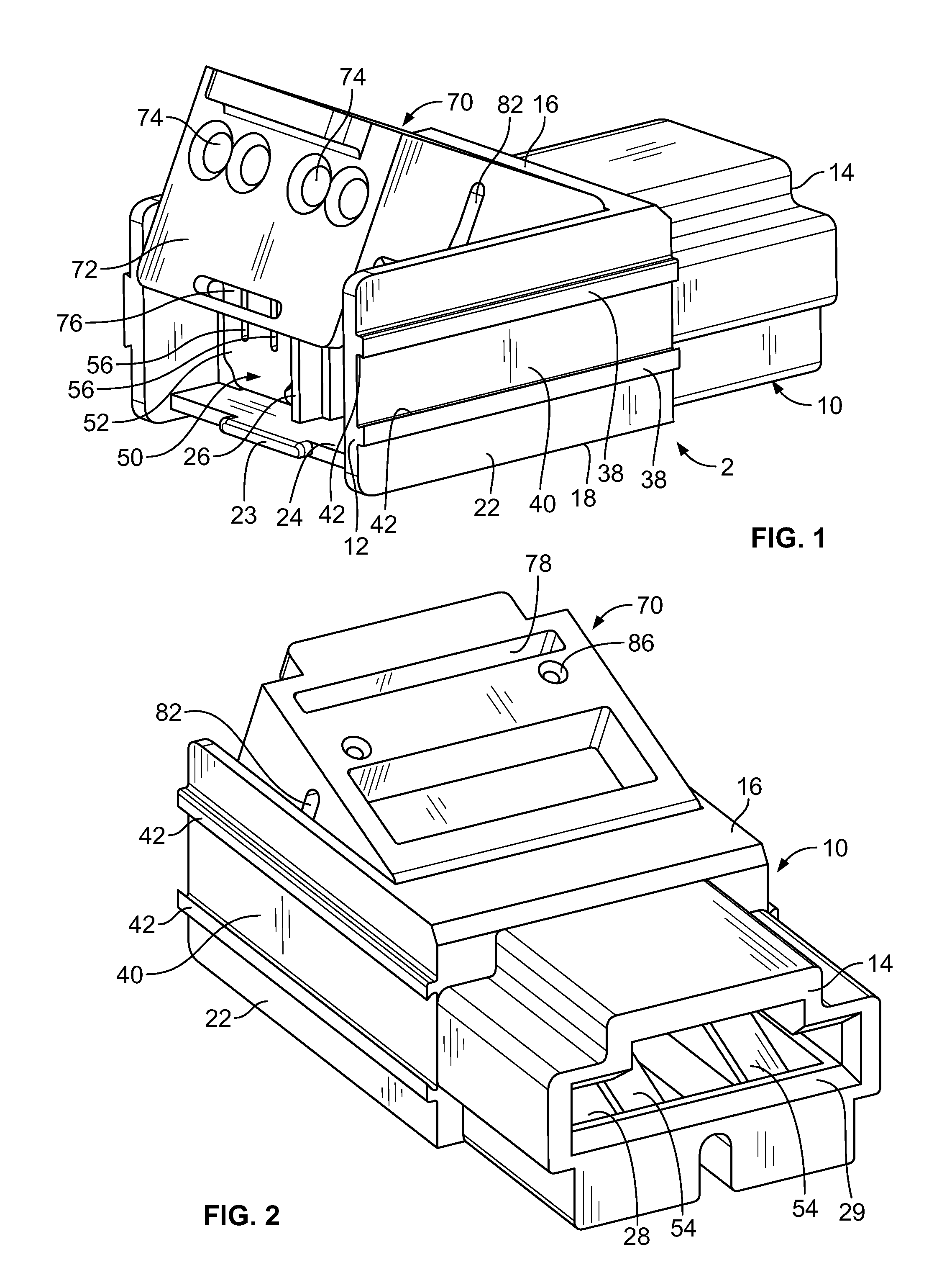
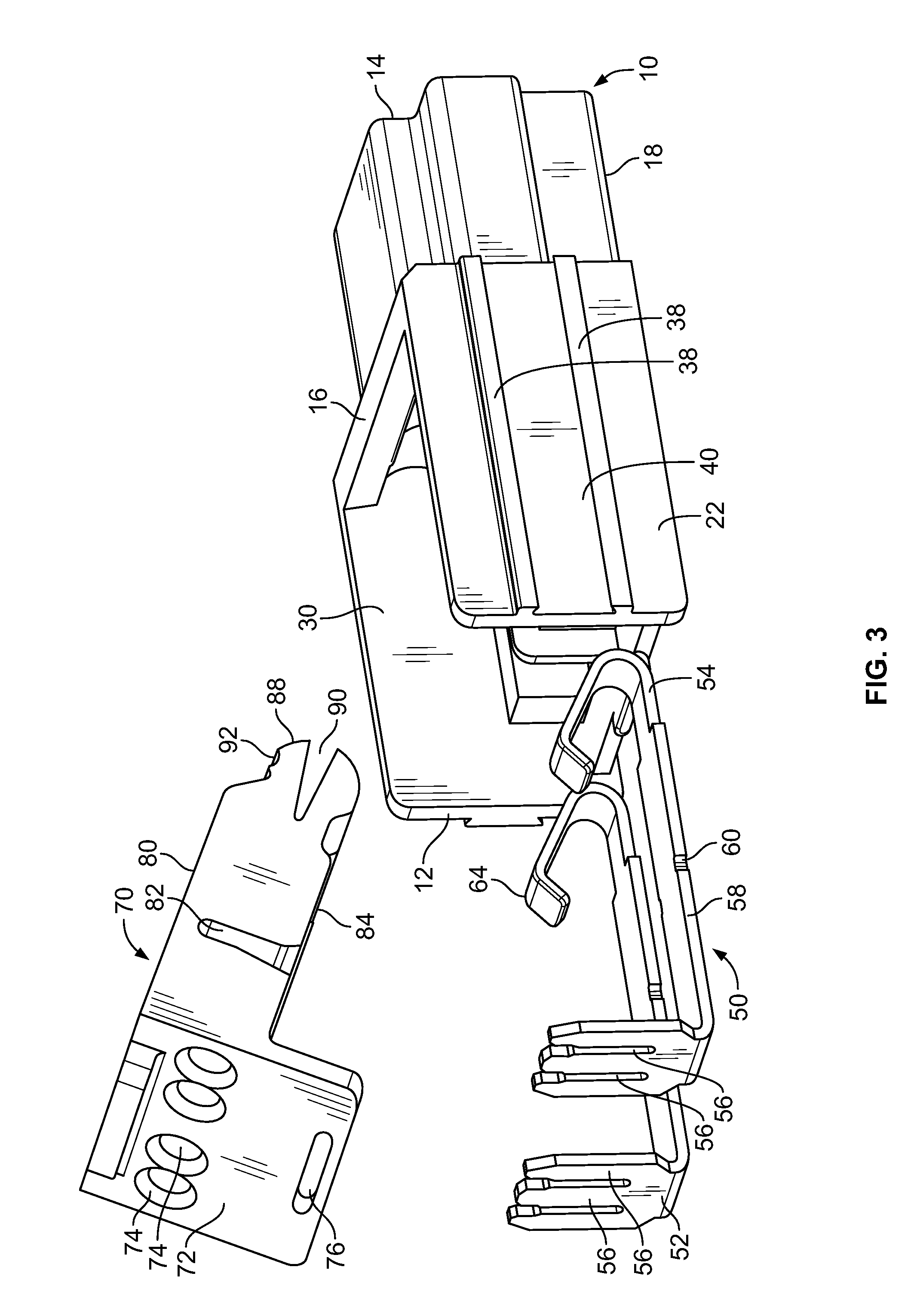
[0023]As shown in FIGS. 1 and 3, a card edge connector 2 has a housing 10, terminals 50 and a stuffer cap 70. While the embodiment shown has two terminals 50 and one stuffer cap 70 installed in the housing 10, other size housings with different numbers of terminals and different size and numbers of stuffer caps can be substituted without departing from the scope of the invention.

[0024]Housing 10 is made of plastic or other similar material that is nonconductive and has the strength and moldability characteristics required. Housing 10 has a wire receiving face 12, a card or circuit board receiving face 14. Top wall 16, bottom wall 18, sidewall 20 and sidewall 22 extend between the wire receiving face 12 and the board receiving face 14. A latching projection 23 extends from the wire receiving face 12. Terminal receiving cavities 24 (FIGS. 7 and 8) extend from the wire receiving face 12 toward the board receiving face 14. As shown in FIGS. 1, 3, 7 and 8, a dividing wall 26 is positione...


PUM


Abstract

A card edge connector and a card edge assembly that utilizes the individual card end connectors are disclosed. The card edge connectors have slotted insulation displacement terminals to connect to wires. Each electrical connector has a housing with first mounting project extends from a first sidewall of the housing and a mounting recess extends from an oppositely facing second sidewall. The mounting projection is dimensioned to be received in the mounting recess of a second electrical connector, thereby allowing the connectors to be mounted to each other. This type of connector assembly allows the connector assembly to be built according to the needs of the end user. This modular aspect of the connector assembly adds flexibility while reducing the overall cost of manufacture. In addition, the use of the slotted insulation displacement terminals further enhances the flexibility of the connector assembly, as various wiring schemes can be effectively and cost efficiently utilized.

Description

FIELD OF THE INVENTION[0001]The present invention is directed to a card edge insulation displacement connector. More particularly, the present invention is directed to a card edge insulation displacement connector that has dual slotted terminals and which can be combined to form a card edge connector assembly.BACKGROUND OF THE INVENTION[0002]With the decreasing size of electronic devices used in most all fields, there is a continuing demand for smaller sized electrical components used in these electronic devices. This is especially so in the telecommunications field with the demand for mobile, lightweight and smaller sized devices. Similarly, in the field of cable communications, smaller sized electronic devices and the related connectors are in demand. For example, the household use of cable communications, both for television and computer connections, is one area where the need for smaller sized and reliable connectors is rapidly expanding.[0003]In the telecommunications field, an...

Claims


Application Information

Patent Timeline
Patent Type & Authority Applications(United States)
IPC IPC(8): H01R12/00
CPCH01R4/2433H01R12/721H01R13/514H01R13/41
Inventor DAILY, CHRISTOPHER GEORGE
Owner TE CONNECTIVITY CORP
Why Eureka
Try Eureka