
Radio Communication System, A Repeater Apparatus and a Control Method of the Repeater

Inactive Publication Date: 2010-02-11
HITACHI LTD
View PDF4 Cites 19 Cited by
  • Summary
  • Abstract
  • Description
  • Claims
  • Application Information

AI Technical Summary

Benefits of technology

[0016]An ultimate object of this invention is to reduce the number of installed base stations which are costly.
[0020]The number of mobile stations connected to the base station is unequal among the base stations, and hence the throughputs of the mobile stations connected to the base station originally having a larger number of connected mobile stations are improved when the number of mobile stations is made uniform among the base stations. As a result, the throughputs of a smaller number of mobile stations are reduced whereas the throughputs of a larger number of mobile stations can be improved.
[0023]To make efficient use of a repeater apparatus to cover a decrease in number of installed base stations.
[0027]With the radio communication system and the repeater apparatus according to one embodiment of this invention, the number of connected mobile stations can be made uniform dynamically among the base stations. As a result, though a decrease in the throughputs of a smaller number of mobile stations is induced, the throughputs of a larger number of mobile stations can be improved. Further, the loads are uniformed among the base stations, whereby idle or almost-nonoperating base stations can be reduced, and the cost-effectiveness of the base station installation can be enhanced. Further, the number of installed base stations can be reduced by introduction of the repeater apparatus so that the costs necessary for the system construction can be suppressed.

Problems solved by technology

A reduction in the number of installed base stations causes two problems.

Method used


Image

  • Radio Communication System, A Repeater Apparatus and a Control Method of the Repeater
  • Radio Communication System, A Repeater Apparatus and a Control Method of the Repeater
  • Radio Communication System, A Repeater Apparatus and a Control Method of the Repeater

Examples


first embodiment

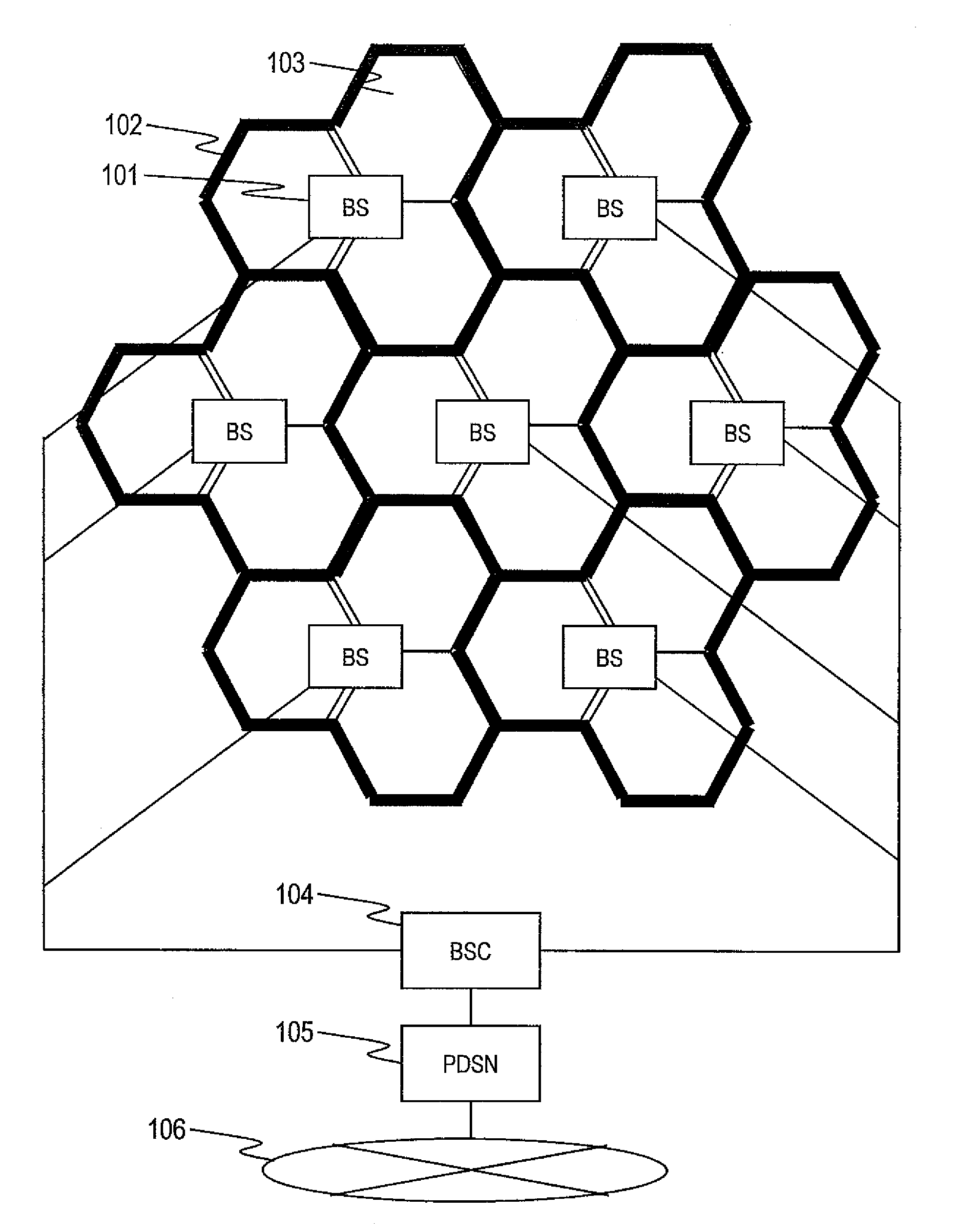
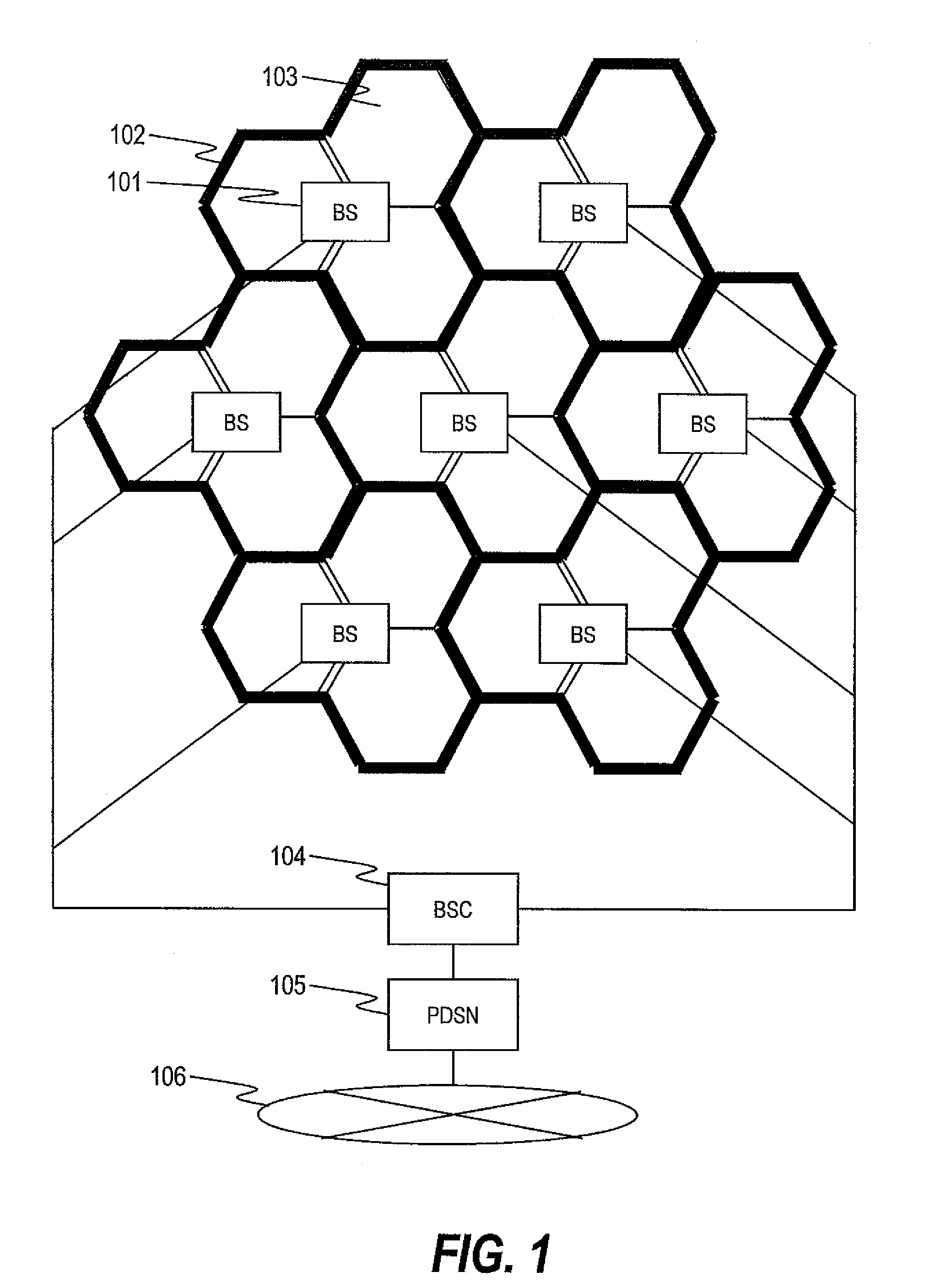
[0064]FIG. 1 is an explanatory diagram illustrating an example of a radio communication system according to this invention.

[0065]Base stations (BS) 101 cover areas (domains surrounded by heavy lines in the example of FIG. 1) of cells 102, respectively, and each cell 102 is divided into a plurality of sectors 103 (three hexagonal domains around each base station 101 in the example of FIG. 1). Each base station 101 exchanges data with another base station or another communication system via a base station control unit (BSC) 104 and a packet data serving node (PDSN) 105. The base station 101 exchanges data with another communication system via an IP network 106.

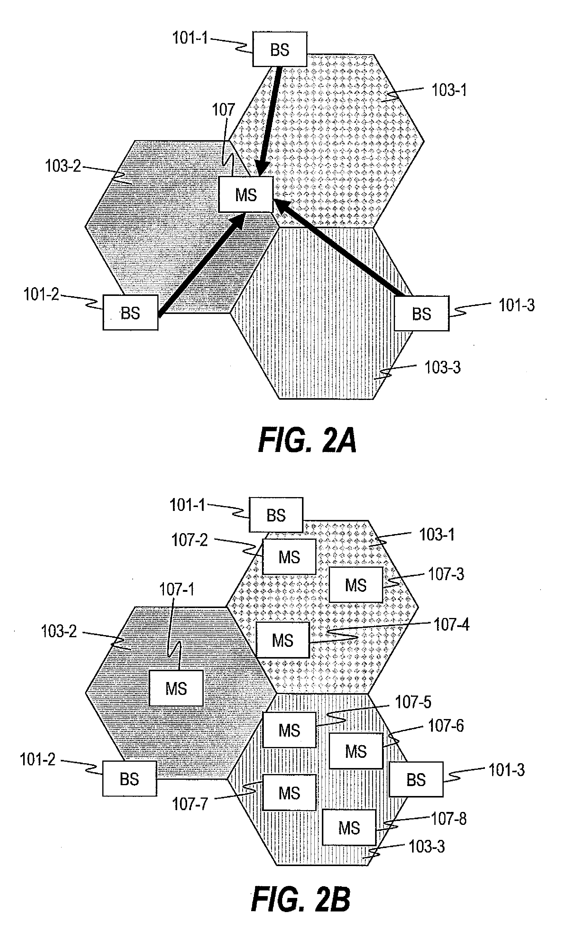
[0066]FIG. 2A is an explanatory diagram illustrating a first problem on a conventional radio communication system.

[0067]A mobile station (MS) 107 implements data communication with a base station 101-2 (desired base station). The mobile station 107 is located at an edge of a sector 103-2 that is covered with the desired base sta...

second embodiment

[0266]Then, a second embodiment for avoiding the above-mentioned concern is described.

[0267]The second embodiment is the same as the first embodiment except for the difference described below.

[0268]FIG. 24 is an explanatory diagram illustrating a configuration of a switch periphery inside of the repeater according to the second embodiment of this invention.

[0269]The basic configuration of the second embodiment is similar to that of the first example illustrated in FIG. 18, but the repeater 108 of the second embodiment includes a variable attenuator 520 instead of the switch 518. The attenuator 520 continuously (or gradually) changes the attenuation to change over the connection between the receiving side repeater sector and the transmitting side repeater sector whereas the switch 518 changes over the connection from on to off (or from off to on). With the above-mentioned operation, the sudden loss of the base station due to the mobile station 107 is prevented, whereby the above-ment...


PUM


Abstract

Provided is a radio communication system including a plurality of base stations and a repeater apparatus, in which the repeater apparatus amplifies and transmits a radio signal received from at least one of the plurality of base stations, and controls a domain in which the radio signal is transmitted based on a traffic amount of each of the plurality of base stations. Accordingly, the number of installed base stations which are costly is reduced, and an operating rate of the respective base stations is gained along with the decrease in number of installed base stations.

Description

CLAIM OF PRIORITY[0001]The present application claims priority from Japanese patent application JP2008-205760 filed on Aug. 8, 2008, the content of which is hereby incorporated by reference into this application.BACKGROUND OF THE INVENTION[0002]A technology disclosed in the present specification relates to a radio communication system including a repeater apparatus and a repeater control unit as constituent elements.[0003]First, the background of a radio mobile communication system is described.[0004]In the radio communication system, a base station device connected to a backbone network and a mobile station device having only a radio I / F transmit data signals (also including audio signals) wirelessly to each other.[0005]As an interface standard of the radio portion, there is known, for example, Ultra Mobile Broadband (UMB). The UMB belongs to a so-called 3.9-th generation mobile communication system. In a standards document, the rule of a method of transmitting the data signal, a c...

Claims


Application Information

Patent Timeline
IPC IPC(8): H04B1/60
CPCH04B7/1555H04W16/26H04W16/08H04J11/0069
Inventor FUJISHIMA, KENZABUROUWANO, KOKI
Owner HITACHI LTD
Learn More