Medical image diagnostic apparatus, medical image measuring method, and medicla image measuring program

a diagnostic apparatus and image technology, applied in the field of medical image diagnostic equipment, can solve problems such as imposing a large burden on the operator, and achieve the effect of reducing the operational burden

Inactive Publication Date: 2010-02-11
HITACHI LTD
View PDF4 Cites 40 Cited by
  • Summary
  • Abstract
  • Description
  • Claims
  • Application Information

AI Technical Summary

Benefits of technology

[0044]According to the present invention, it is possible to provide a medical image diagnostic apparatus which mitigates an operational burden at the time when measurement processing is performed by use of a medical image.

Problems solved by technology

These operations impose a large burden on an operator who examines a large number of medical images every day.

Method used


Image

  • Medical image diagnostic apparatus, medical image measuring method, and medicla image measuring program
  • Medical image diagnostic apparatus, medical image measuring method, and medicla image measuring program
  • Medical image diagnostic apparatus, medical image measuring method, and medicla image measuring program

Examples


first embodiment

2. First Embodiment

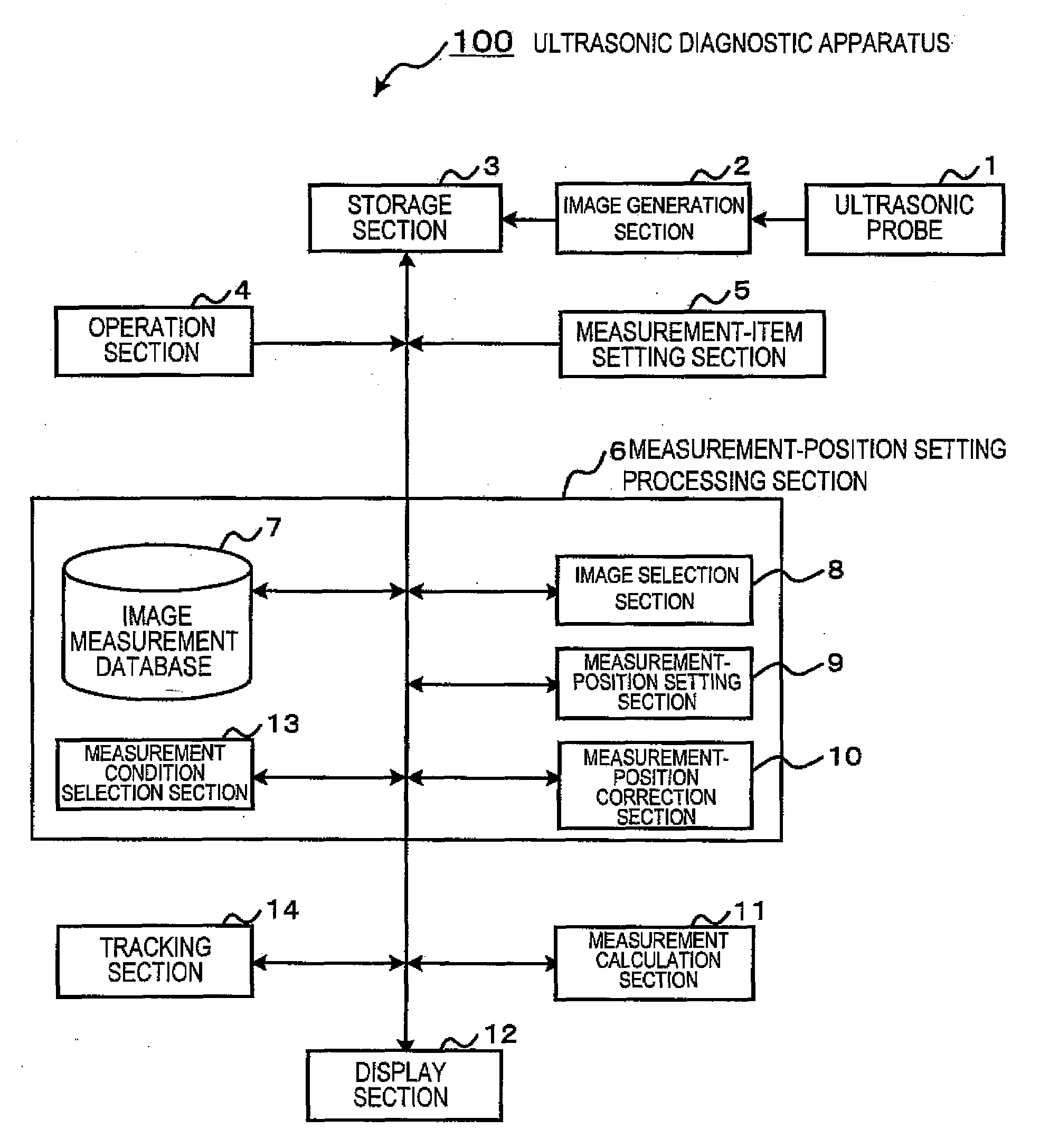
[0161]Next, an operation of the measurement-position setting processing section 6 according to a first embodiment will be described with reference to FIGS. 2 to 5.

(2-1. Image Measurement Database 7)

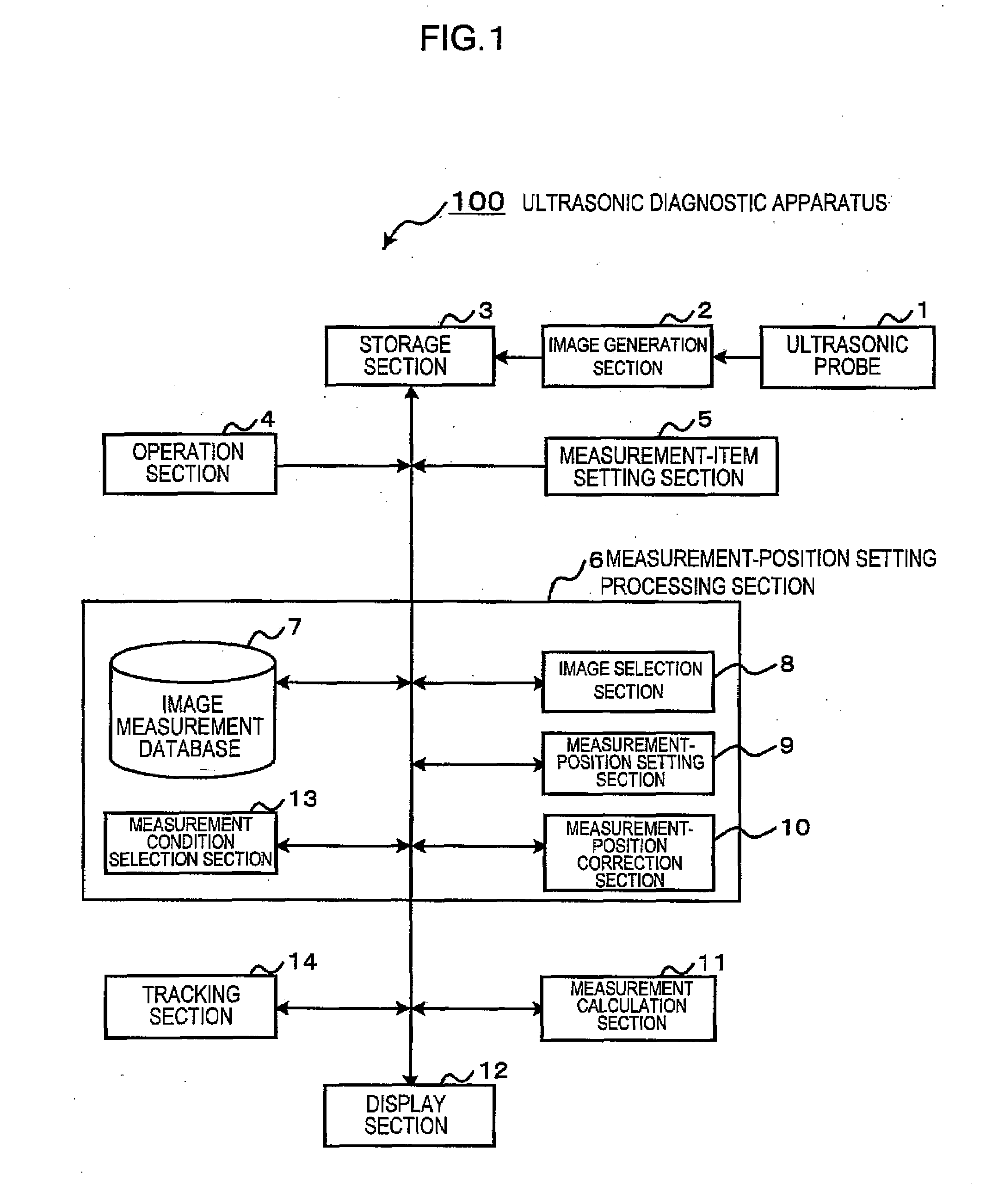
[0162]FIG. 2 is a diagram showing an example of the image measurement database 7.

[0163]The image measurement database 7 holds a plurality of records of image measurement information 22. The image measurement information 22 is information regarding an image and a measurement position which were used for measurement in the past. The image measurement information 22 includes measurement position information 23, image information 24, and measurement condition information 25, which are related to a certain single measurement and are held as a single record. Further, the image measurement information 22 may include image information 26 of a region around the measurement position indicated by the measurement position information 23.

[0164]The measurement position information 23...

second embodiment

3. Second Embodiment

[0188]Next, a second embodiment will be described with reference to FIGS. 6 and 7.

[0189]In the first embodiment, the one-to-one image recognition calculation is performed for comparison between the input image information 21 and the image information 24 of the image measurement database 7. In the second embodiment, image recognition calculation is performed so as to compare the input image information 21 with representative image information 42, which represents images of each category, before performance of the one-to-one image recognition calculation for comparison between the input image information 21 and the image information 24.

(3-1. Image Measurement Database 7)

[0190]FIG. 6 is a diagram showing an example of the image measurement database 7.

[0191]The image measurement database 7 holds a plurality of categorized image measurement databases 41-1, 41-2, etc. The categorized image measurement databases 41-1, 41-2, etc. each hold the representative image inform...

third embodiment

4. Third Embodiment

[0202]Next, a third embodiment will be described with reference to FIGS. 8 and 9.

[0203]In the first embodiment, the one-to-one image recognition calculation is performed for comparison between the input image information 21 and the image information 24 of the image measurement database 7. In the third embodiment, measurement condition recognition calculation is also performed for comparison between the input measurement conditions 43 and the measurement condition information 25 of the image measurement database 7.

(4-1. Image Measurement Database 7)

[0204]FIG. 8 is a diagram showing an example of the image measurement database 7.

[0205]The image measurement database 7 of the third embodiment is identical with the image measurement database 7 of the first embodiment. In the third embodiment, recognition calculation is performed for comparison between the input image information 21 and the input measurement conditions 43 and each record of the image measurement informa...


PUM


Abstract

[Objective] Providing a medical image diagnostic apparatus which can mitigate an operational burden at the time when measurement processing is performed by use of a medical image.
[Means for Solution] An ultrasonic diagnostic apparatus 100 acquires input image information, which is image data of a subject, and holds it in a storage section 3. An image selection section 8 performs image recognition calculation for comparison between the input image information and past image information pieces of an image measurement database 7. When the image recognition has succeeded, a measurement-position setting section 9 refers to a record of image measurement information including a past image information piece most similar to the input image information, retrieves measurement position information of the record, and sets it. A measurement-position setting processing section 6 displays the measurement position on a display section 12 such that it is superimposed on the input image information 21. A measurement calculation section 11 performs measurement calculation for the measurement position set by the measurement-position setting section 9, and displays measurement results on the display section 12. The measurement-position setting processing section 6 updates the image measurement database 7 on the basis of the input image information, the measurement position set by the measurement-position setting section 9, etc.

Description

TECHNICAL FIELD[0001]The present invention relates to a medical image diagnostic apparatus which measures an organ tissue by use of an image thereof.BACKGROUND ART[0002]In the case of a conventional medical image diagnostic apparatus, an operator designates a measurement position on an acquired image by use of an input device such as a mouse, a trackball, or the like. Subsequently, the medical image diagnostic apparatus performs calculation for measurement, and displays measurement results on a display screen.[0003]A measurement application program is used for designation of the measurement position or point. When the operator designates a plurality of points on an image, the measurement application program measures a distance between the points, the area of a region defined by the points, or the volume of a space defined by the points. When the operator sets a predetermined region on an image, the measurement application program calculates measurement values within the region.[0004...

Claims


Application Information

Patent Timeline
Patent Type & Authority Applications(United States)
IPC IPC(8): A61B8/14
CPCA61B6/503A61B6/504A61B6/563A61B8/08A61B8/0891A61B8/565A61B8/463G06T7/0044G06T2207/10081G06T2207/10088G06T2207/10132G06T2207/30048G06F19/321G06T7/74G16H30/20G16H30/40G16H50/20
Inventor CHOUNO, TOMOAKI
Owner HITACHI LTD
Why Eureka
Try Eureka