Scanning probe microscope with automatic probe replacement function

a technology of automatic replacement and scanning probe, which is applied in the field of scanning probe microscope, can solve the problems of inconvenient operation, damage to the probe or the tip of the probe, and conventional spm operation

Active Publication Date: 2010-02-11
PARK SYST CORP
View PDF3 Cites 15 Cited by
  • Summary
  • Abstract
  • Description
  • Claims
  • Application Information

AI Technical Summary

Problems solved by technology

As described above, since the tip of the probe in the conventional SPM moves while contacting the surface of the sample or maintaining a constant distance from the surface of the sample, the probe or the tip of the probe can be damaged when the conventional SPM operates.
However, in the conventional SPM, the tip of the probe must be manually replaced by a user, and thus, it is inconvenient to do so.

Method used


Image

  • Scanning probe microscope with automatic probe replacement function
  • Scanning probe microscope with automatic probe replacement function
  • Scanning probe microscope with automatic probe replacement function

Examples


Embodiment Construction

[0034]Hereinafter, the present invention will be described in detail with reference to accompanying drawings.

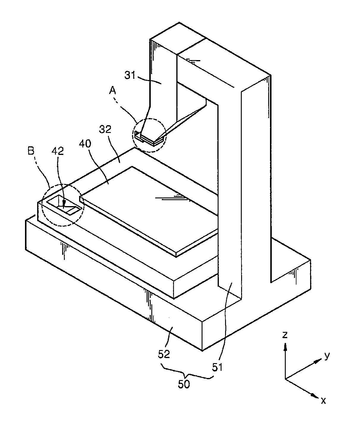
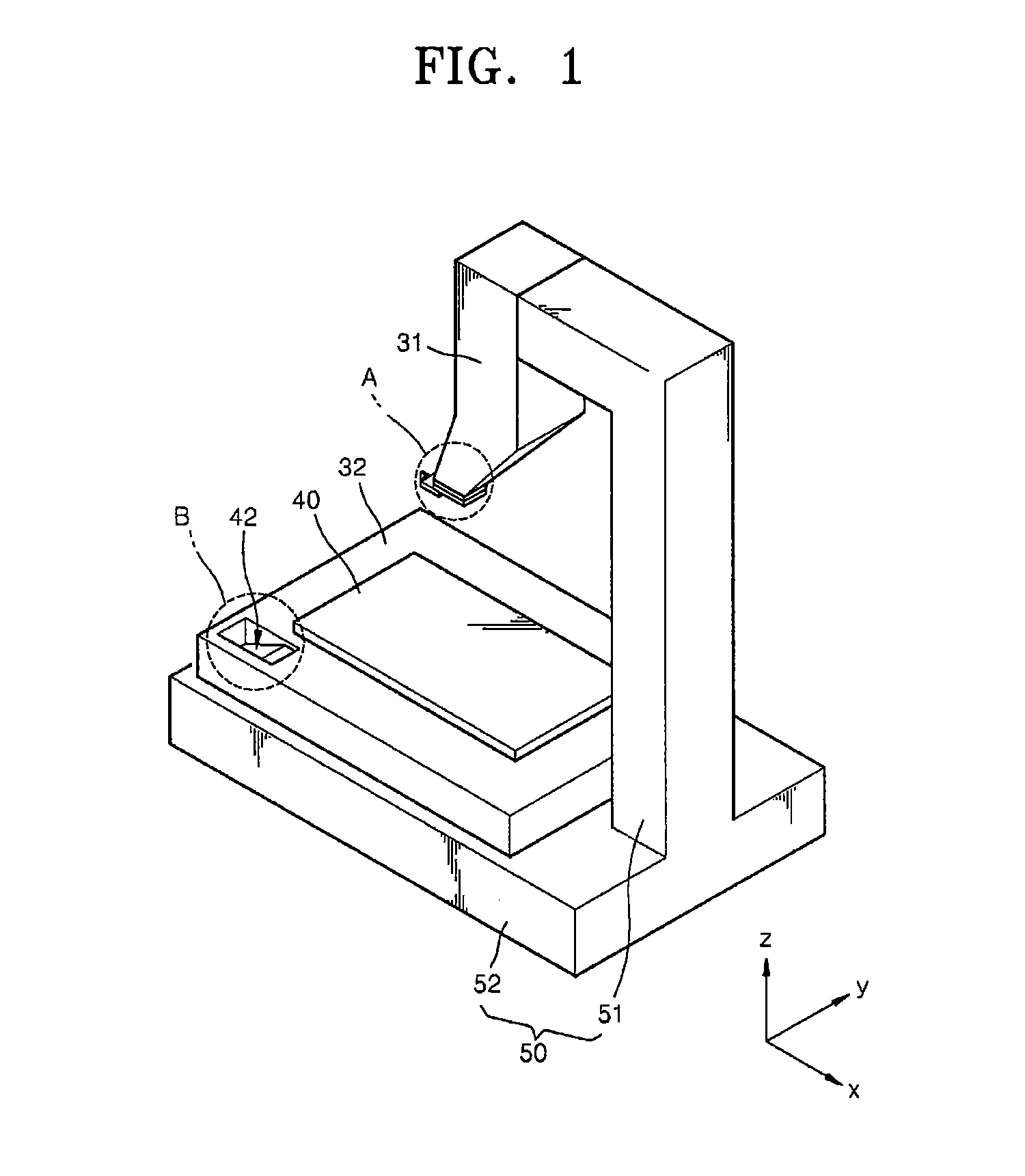
[0035]FIG. 1 is a schematic perspective view of a scanning probe microscope (SPM) according to an embodiment of the present invention. Referring to FIG. 1, the SPM according to the current embodiment includes a first scanner 31, a second scanner 32, and a tray 42 that stores a spare probe. If necessary, the SPM can further include a frame 50 that includes a first frame 51 supporting the first scanner 31 and a second frame 52 supporting the second scanner 32, as shown in FIG. 1. Additionally, a position of the tray 42 is not limited to the position shown in FIG. 1, and thus, the position of the tray 42 can be located on various other locations of the SPM.

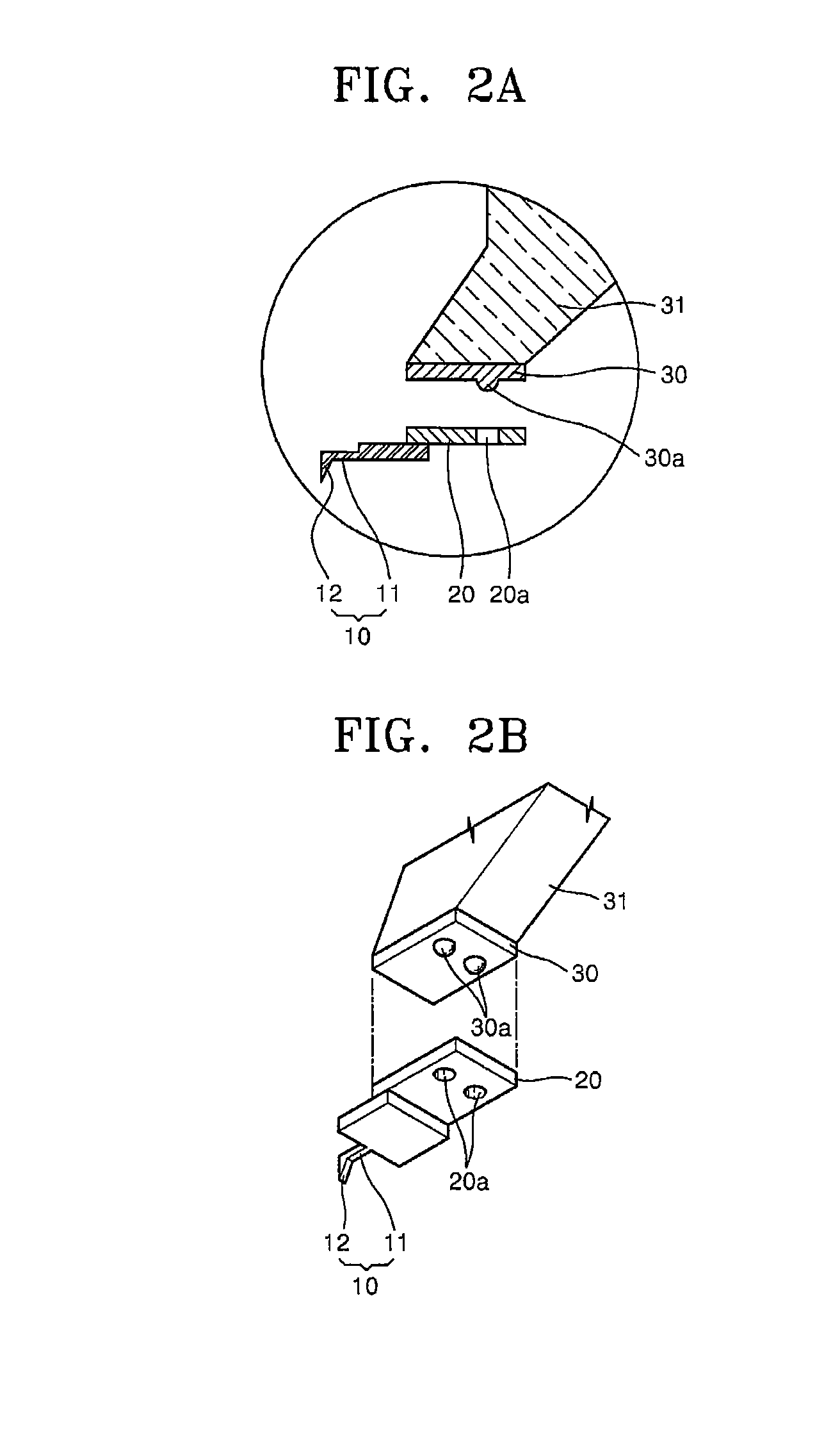
[0036]The first scanner 31 includes a carrier holder 30 (refer to FIG. 2A) on an end portion thereof, and moves the carrier holder 30 in a straight line in a z-axis direction. Hence, when a carrier 20, to which the probe is at...


PUM


Abstract

An automatic probe exchange system for a scanning probe microscope (SPM) exchanges probes between a probe mount on the SPM and a probe mount on a probe tray based on differential magnetic force. When the magnetic force on the SPM side is greater, the probe is attached to the probe mount on the SPM. When the magnetic force on the probe tray side is greater, the probe is attached to the probe mount on the probe tray. The magnetic force on the probe tray side is varied by moving the magnets that generate the magnetic force on the probe tray side closer to or further from the probe.

Description

CROSS-REFERENCE TO RELATED APPLICATIONS[0001]This application is a continuation-in-part of U.S. patent application Ser. No. 11 / 872,614, filed on Oct. 15, 2007, now pending.BACKGROUND OF THE INVENTION[0002]1. Field of the Invention[0003]The present invention relates to a scanning probe microscope, a probe of which can be automatically replaced, and more particularly, to a scanning probe microscope, a probe of which can be automatically replaced and the replacement probe can be attached to an exact position.[0004]2. Description of the Related Art[0005]Scanning probe microscopes (SPMs) are microscopes having a resolution in the nano-scale range, and show surfaces of samples or electrical properties of the samples as images. Some examples of SPMs are atomic force microscopes (AFMs), magnetic force microscopes (MFMs), and scanning capacitance microscopes (SCMs).[0006]In a conventional SPM, a tip of a probe moves while contacting a surface of a sample or moves while maintaining a predeter...

Claims


Application Information

Patent Timeline
Patent Type & Authority Applications(United States)
IPC IPC(8): G01Q70/02G01Q70/00
CPCG01Q70/02B82Y35/00
Inventor JO, HYEONG CHANLIM, HONG JAESHIN, SEUNG JUNKIM, JOON HUIKIM, YONG SEOKPARK, SANG-IL
Owner PARK SYST CORP
Why Eureka
Try Eureka