Removable probe sensor assembly and scanning probe microscope
What is Al technical title?
Al technical title is built by PatSnap Al team. It summarizes the technical point description of the patent document.
a scanning probe and sensor assembly technology, applied in the direction of instruments, mechanical measuring arrangements, mechanical roughness/irregularity measurements, etc., can solve the problems of stylus tip blunders, stylus or cantilever damage, etc., to prevent damage to the vertical and lateral drive mechanism
Inactive Publication Date: 2005-06-28
RAYMAX TECH
View PDF21 Cites 12 Cited by
Summary
Abstract
Description
Claims
Application Information
AI Technical Summary
This helps you quickly interpret patents by identifying the three key elements:
Problems solved by technology
Method used
Benefits of technology
[0024]I adjustment of the laser beam is accomplished while the probe illuminator assembly is removed from the microscope thereby preventing damage to the ve
Problems solved by technology
This may result from a blunted stylus tip typically caused by wear of, or by small particles that adhere to, the tip as it scans over the sample.
Also, the stylus or the cantilever, or both can break, thus necessitating replacement of the probe assembly.
In some instances the resulting stylus may have an improper shape, such as, for example an aspect ratio or a nonsymetry that will prevent its use.
When such a stylus is used to scan a sample surface, the image obtained would be distorted.
These microscopes have a disadvantage stemming from the limited force capability of the lateral and vertical drive mechanisms.
The mechanical resonance of these scanning mechanisms is also undesirably low with large moving mass.
But, these microscopes also have the disadvantage as described above in that they move the sample under the stationary stylus.
Further, the assemblies are too massive to be mounted to the lateral and vertical drive mechanisms because they permit adjustment of the beam path or probe position only while the assembly is mounted to the microscope.
However, the relatively great mass of the moving part of these mic
Method used
Image
Click on the blue label to locate the original text in one second.
Reading with bidirectional positioning of images and text.
Examples
Embodiment Construction
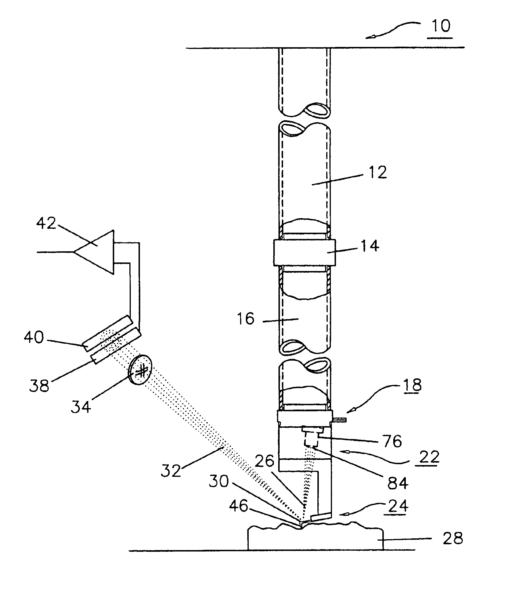
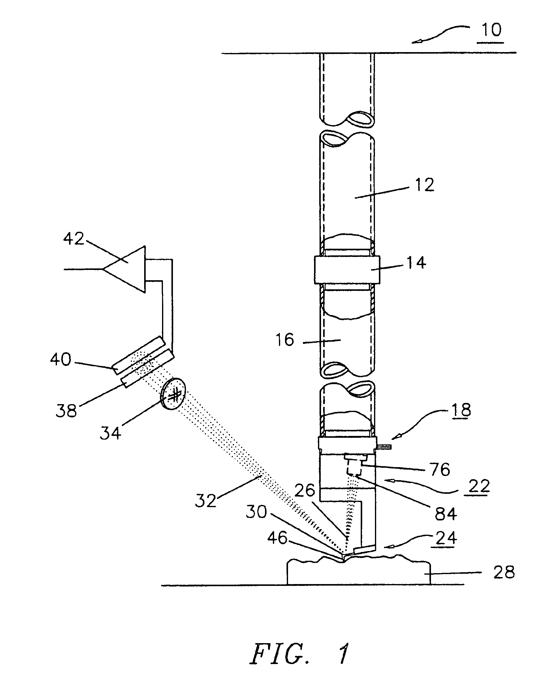
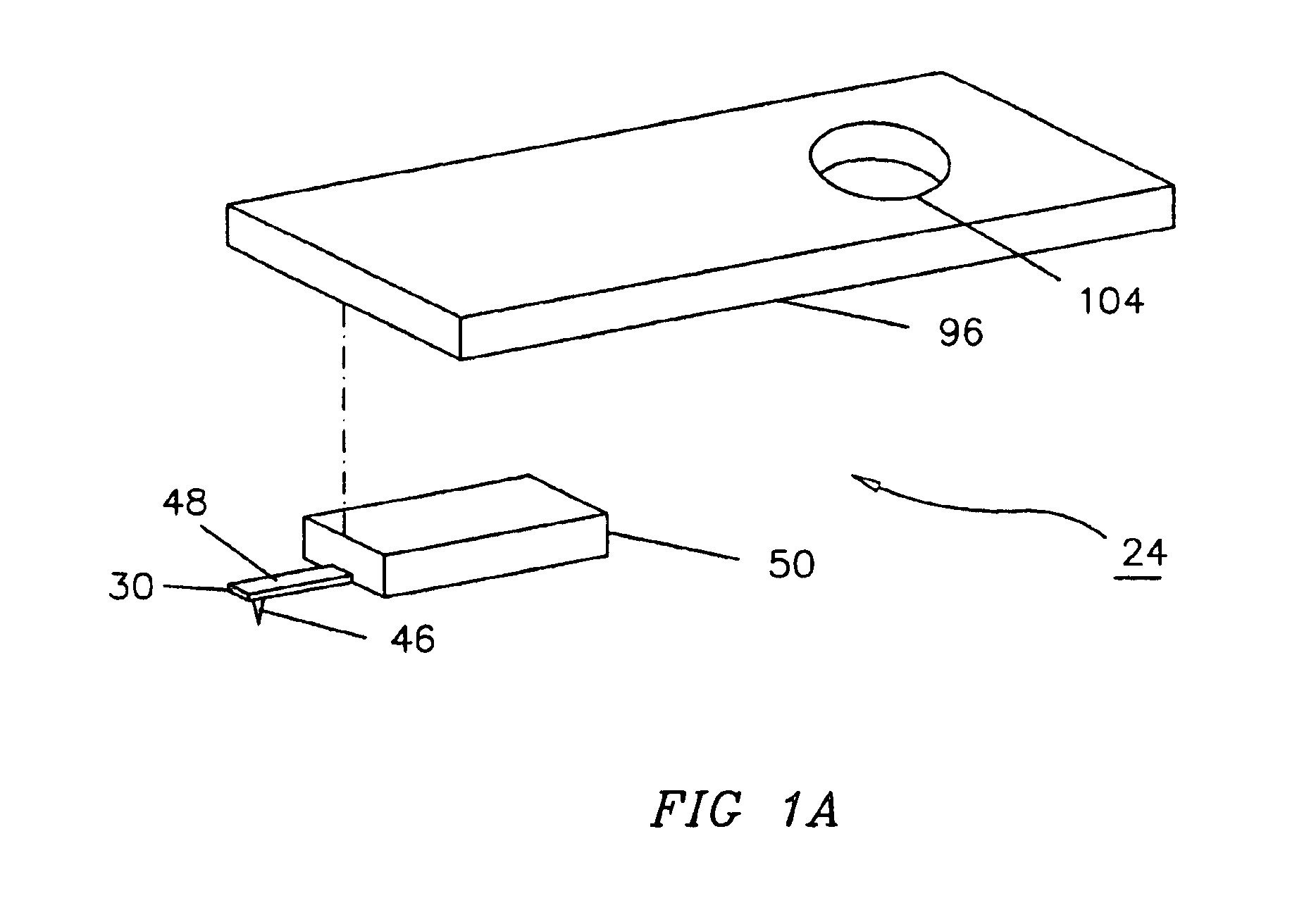
[0044]FIG. 1 illustrates a preferred embodiment of the invention. A microscope frame 10 supports a lateral driver 12 coupled to a vertical driver 16 by a coupler 14 . Vertical driver 16 supports a receiver assembly 18 . A removable probe illuminator assembly 22 supports a laser 76 with a laser focusing lens 84 and a probe assembly 24 detailed in FIG. 1A. Probe illuminator assembly 22 is shown in FIG. 2. Laser 76 creates a laser beam 26. Laser beam 26 reflects off a cantilever 30, which supports a stylus 46, to form a reflected beam 32. Stylus 46 follows the topography of a sample 28. Reflected beam 32 passes through a beam sizing lens 34 and impinges on a first photodiode 38 or a second photodiode 40 or both. A difference amplifier 42 receives the output signals from photodiodes 38 and 40. Beam sizing lens 34 is optional and either increases or decreases the diameter of the beam to a value that matches the light sensitive areas of photodiodes 38 and 40. The focal lengths and positio...
PUM
Abstract
A scanning force microscope system that employs a laser (76) and a probe assembly (24) mounted in a removable probe illuminator assembly (22), that is mounted to the moving portion of a scanning mechanism. The probe illuminator assembly may be removed from the microscope to permit alignment of said laser beam onto a cantilever (30) after removal. This prevents damage to, and shortens alignment time of, the microscope during replacement and alignment of the probe assembly. The scanning probe microscope assembly (240) supports a scanning probe microscope (244). Scanning probe microscope (244) holds a removable probe sensor assembly (242). Removable probe sensor assembly (242) may be transported and conveniently attached to the adjustment station (250) where the probe sensor assembly parameters may be observed and adjusted if necessary. The probe sensor assembly (242) may then be attached to the scanning probe microscope (244).
Description
CROSS REFERENCE TO RELATED APPLICATIONS[0001]This application is a divisional application of U.S. patent application Ser. No. 10 / 190,404, filed Jul. 7, 2002, now U.S. Pat. No. 6,748,794. U.S. patent application Ser. No. 10 / 190,404 is a divisional application of U.S. patent application Ser. No. 09 / 699,803, filed Oct. 30, 2002, now U.S. Pat. No. 6,415,654. U.S. patent application Ser. No. 09 / 699,803 a divisional application of U.S. patent application Ser. No. 09 / 253,462, filed Feb. 19, 1999, now U.S. Pat. No. 6,138,503, which is a continuation-in-part of U.S. patent application Ser. No. 08 / 951,365, filed Oct. 16, 1997, now U.S. Pat. No. 5,874,669.BACKGROUND OF THE INVENTION[0002]A. Field of the Invention[0003]The present invention relates to the field of scanning probe microscopes, including those which use light beam detection schemes.[0004]B. Description of the Prior Art[0005]Scanning force microscopes, also referred to as atomic force microscopes, can resolve features of matter to ...
Claims
Application Information
Patent Timeline
Application Date:The date an application was filed.
Publication Date:The date a patent or application was officially published.
First Publication Date:The earliest publication date of a patent with the same application number.
Issue Date:Publication date of the patent grant document.
PCT Entry Date:The Entry date of PCT National Phase.
Estimated Expiry Date:The statutory expiry date of a patent right according to the Patent Law, and it is the longest term of protection that the patent right can achieve without the termination of the patent right due to other reasons(Term extension factor has been taken into account ).
Invalid Date:Actual expiry date is based on effective date or publication date of legal transaction data of invalid patent.