Method for driving a scanning probe microscope at elevated scan frequencies

a scanning probe and scanning frequency technology, applied in scanning probe techniques, instruments, nanotechnology, etc., can solve the problems of limiting the scan speed of scanning probe microscopes, the time resolution of commercially available spm instruments is one of their most severe limitations, and the dedicated spms do not have enough time resolution to allow, so as to improve the time resolution of commercial scanning probe microscopes, improve the scanning capability, and save time and money. , the effect of increasing the scanning speed

Active Publication Date: 2012-03-15
CONSIGLIO NAT DELLE RICERCHE
View PDF7 Cites 11 Cited by
  • Summary
  • Abstract
  • Description
  • Claims
  • Application Information

AI Technical Summary

Benefits of technology

[0018]The objective of the present invention is to boost the time resolution of commercial scanning probe microscopes without having to recur to a customized design of the microscope assembly which involves considerable efforts in terms of time and money investments. In other words, the object of the invention is to upgrade virtually any scanning probe microscope with fast scanning capability without any modification of the scanner and the existing control system hardware.

Problems solved by technology

The time resolution of commercially available SPM instruments is one of their most severe limitations since the typical image acquisition times are of the order of seconds or more.
However, most of these dedicated SPMs do not have enough time resolution to allow for observing manipulation events and local, non equilibrium dynamics on the time scale of some milliseconds, i.e. imaging rates of video rate and beyond.
The main factors that limit the scan speed in scanning probe microscopes are the limited bandwidth of the components of the electronic control systems, namely the control and signal detection electronics, and the mechanical resonances of the scanner.
A critical limit to the time resolution is given by mechanical instabilities of the SPMs that appear as soon as the scanning frequencies reach or exceed the intrinsic resonance frequencies of the imaging system.
Moreover, data acquisition and real-time processing speed can also limit the achievable performance: for instance, the acquisition of a 100×100 pixels2 image at an imaging rate of 100 Hz with 16 bits requires the acquisition system to handle a minimum data stream of about 2 Mb / s (data transmission, elaboration and visualization).
While suitable, high bandwidth and high power operational amplifiers can be readily found on the market, high bandwidth preamplifiers with low noise characteristics in the 109V / A (108V / A) amplification range and a frequency-independent response are not commercially available above the 50 kHz (200 kHz) bandwidth.
This approach has the obvious drawback of requiring a custom design of the preamplifier, whereas in our experience, with standard 200 kHz cutoff and suitable signal post-processing, useful signal to noise ratio can be achieved also at much higher frequencies (up to 800 kHz).
When imaging in constant current mode, the limited response time of the feedback system is also of concern.
The most serious limitation to the scan speed, however, is imposed by the mechanical resonance frequencies of the scanner assembly.
When the scanner is driven close to resonance frequencies, two major problems arise: i) the amplitude of the probe movements in the direction of the stimulus (i.e. the amplitude of the tip oscillation or scan area) cannot be a priori predicted anymore, and ii) a coupling to other directions (orthogonal to the surface or in the slow scan direction) can occur, resulting in tip crashes and / or distorted imaging.
The problem of piezo resonances in the direction orthogonal to the surface (that impose a limit to the scan speed) has been tackled by developing SPM scanners with very high eigenfrequencies or by using suitable active damping / vibration compensation schemes, which, however, only partially limit the effects of such resonances.
In other words, not all the mechanical resonances harm the resolution of the STM, but a method is missing that determines unequivocally which resonances are harmful and have to be avoided.
However, the design, testing and commissioning process for these instruments involves a substantial effort in terms of time and money investment, not to speak about the highly specialized technical know-how that is required.
The complexity of this approach is clearly unbearable for most research labs interested in fast SPM measurements.
On the contrary, little or no attention has been paid to the possibility of driving commercially available, non-tailored SPMs at high imaging speed, owing to the lack of knowledge on how to deal with the presence of resonant modes of the scanner within the range of the scan frequencies of interest.
Conceptually speaking, the simplest solution is to use a capacitive or inductive displacement sensor, but this method is not so appealing since it requires an invasive, non-trivial modification of the scanner head.

Method used


Image

  • Method for driving a scanning probe microscope at elevated scan frequencies
  • Method for driving a scanning probe microscope at elevated scan frequencies
  • Method for driving a scanning probe microscope at elevated scan frequencies

Examples


Embodiment Construction

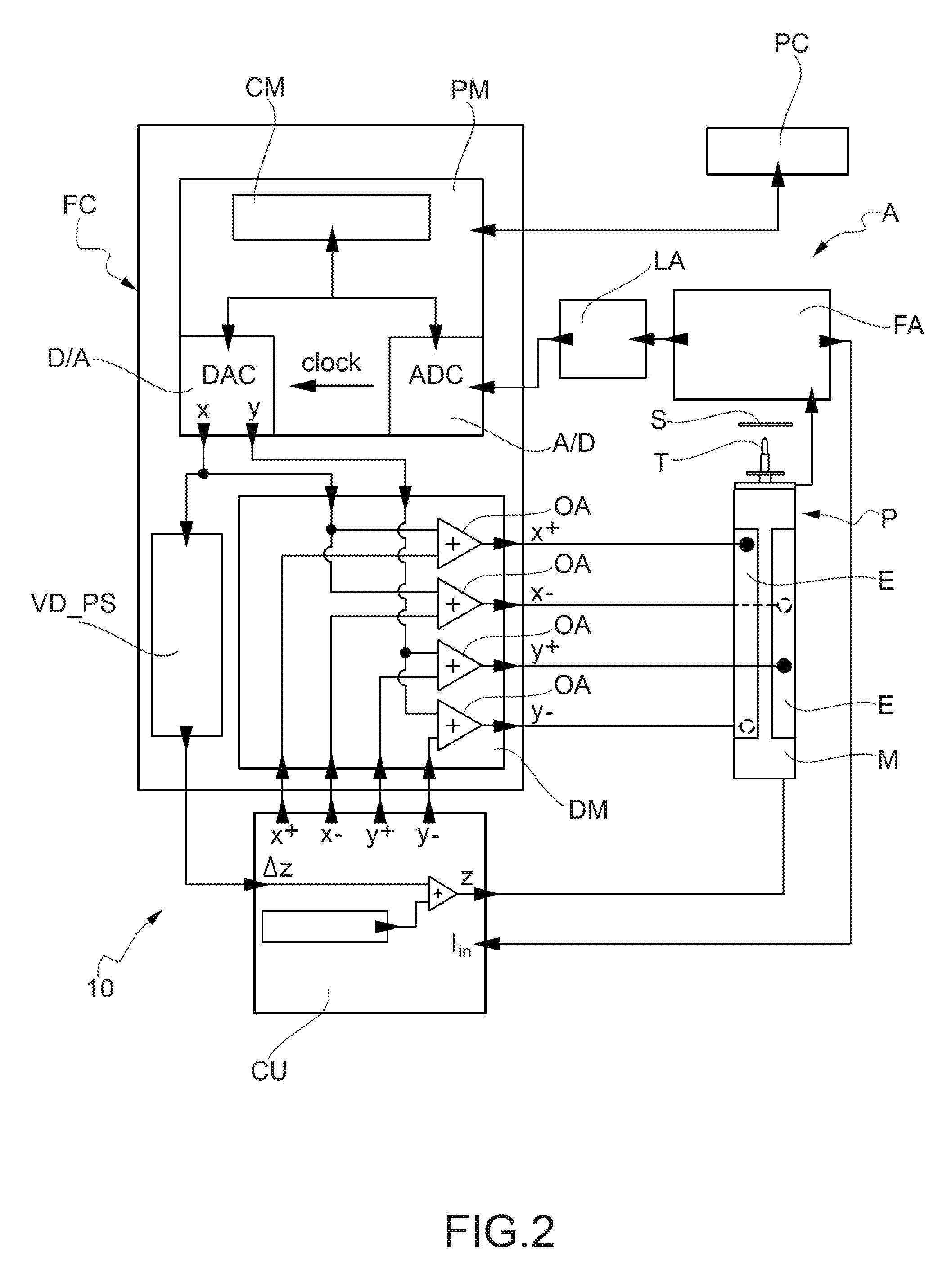
[0026]With reference to FIG. 2, the arrangement of the SPM instrumentation according to the invention is shown, where like references are used to refer to the same components as defined in FIG. 1. A scanning tunneling microscopy arrangement 10 is here below disclosed as a preferable embodiment, but a skilled person would clearly realize that the method of the invention is adapted for any technique of scanning probe microscopy.

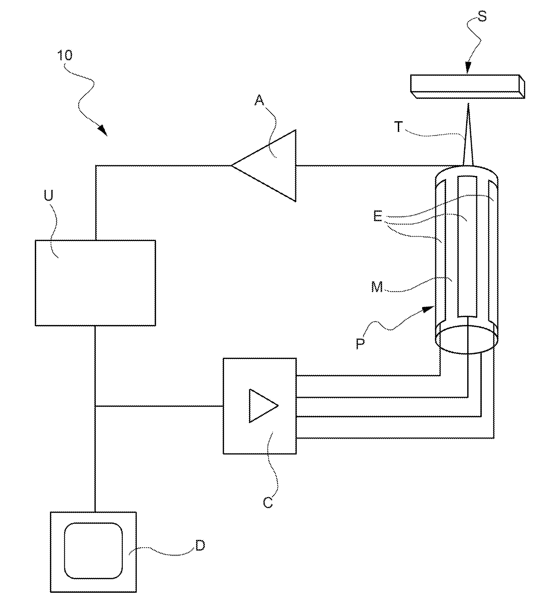
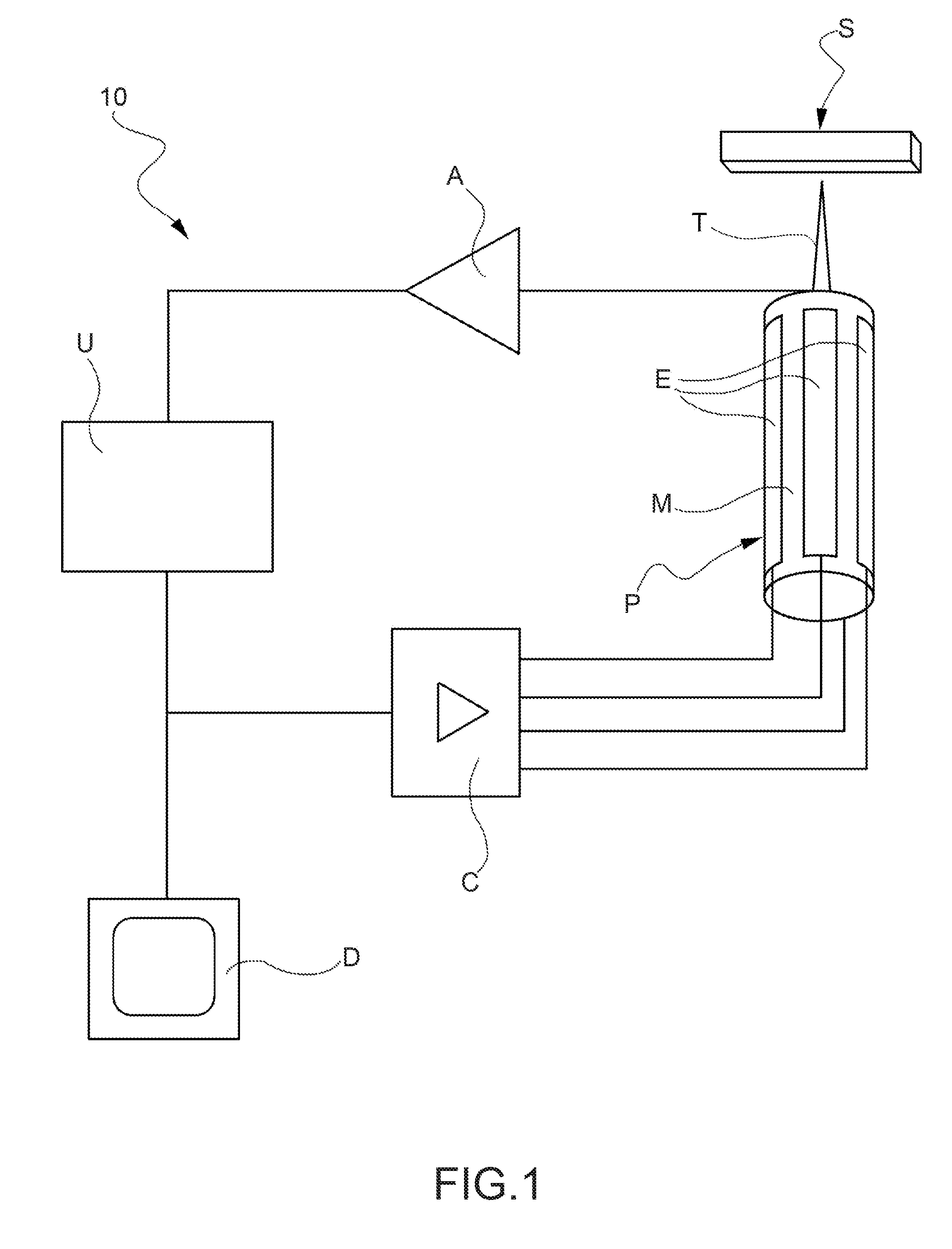
[0027]A probe P associated with a specimen S to be imaged is shown, which comprises a scanning element, such as a sharp tip T or cantilever, carried at the end of a piezo-electric support member M. The piezo-electric member allows for performing both distance regulation between the tip and surface and scanning of the specimen under investigation. The piezo-electric member is controlled so as to move the tip in the directions parallel to the surface of the specimen (commonly identified by x- and y-axes) for achieving the scanning of the specimen surface, and to ...


PUM


Abstract

A method for operating a scanning probe microscope at elevated scan frequencies has a characterization stage of sweeping a plurality of excitation frequencies of the vertical displacement of the scanning element; measuring the value attained by the reading parameter at the excitation frequencies; and identifying plateau regions of the response spectrum of the reading parameter. The reading parameter variation is limited within a predetermined range over a predefined frequency interval, thereby defining corresponding fast scanning frequency windows in which the microscope assembly is sufficiently stable to yield a lateral resolution comparable to the one obtained during slow measurements. The measurement stage includes driving the scanning element along at least a scanning trajectory over the surface of the specimen at a frequency selected among the frequencies included in a fast scanning frequency window.

Description

[0001]This application claims benefit of Serial No. 10176633.5, filed 14 Sep. 2010 in the European Patent Office and which application is incorporated herein by reference. To the extent appropriate, a claim of priority is made to the above disclosed applications.FIELD OF THE INVENTION[0002]The present invention relates to scanning probe microscopes, and more specifically to a method for driving a scanning probe microscope.[0003]Scanning probe microscopes (SPM) provide the ultimate spatial resolution at the atomic and molecular level. These local probes allow not only for imaging, but also for manipulating objects at the nanometer scale, in various environments, from vacuum and air to liquid and electrochemical cells.[0004]A scanning probe microscope forms images of surfaces by means of a physical probe that scans the specimen. An image of the surface is obtained by mechanically moving the probe in a raster scan over the specimen, line by line, and recording the probe-surface interac...

Claims


Application Information

Patent Timeline
Patent Type & Authority Applications(United States)
IPC IPC(8): G01Q10/00
CPCG01Q10/06B82Y35/00
Inventor ESCH, FRIEDRICHDRI, CARLOCOMELLI, GIOVANNIAFRICH, CRISTINASPESSOT, ALESSIO
Owner CONSIGLIO NAT DELLE RICERCHE
Why Eureka
Try Eureka