
Multi-function multi-hole drilling rig

a multi-functional, drilling rig technology, applied in the direction of drilling rods, drilling pipes, borehole/well accessories, etc., to achieve the effect of eliminating the need for slips

Active Publication Date: 2010-02-18
NAT OILWELL VARCO LP
View PDF13 Cites 51 Cited by
  • Summary
  • Abstract
  • Description
  • Claims
  • Application Information

AI Technical Summary

Benefits of technology

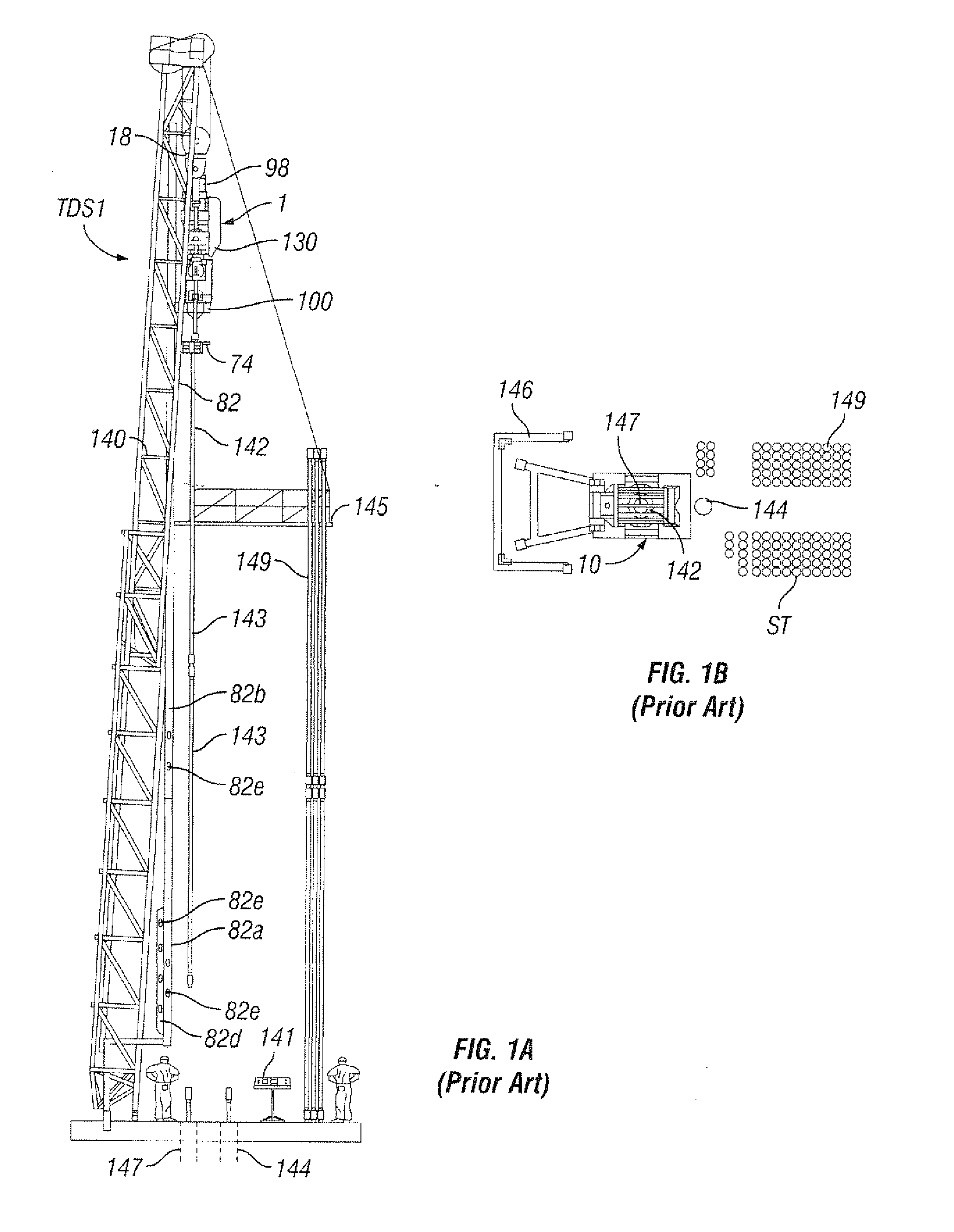
[0023]In certain aspects, drilling machines, tripping machines, and casing running machines according to the present invention have a pipe racking system, as is traditional, in front of the machine(s) (e.g. as in many known cases in which the hole to be drilled is between the drilling machine and the pipe racking system and setback area); but in other aspects according to the present invention, a pipe racking system is located behind the machine rather then in front of the machine. In certain aspects according to the present invention, a pipe racking system uses the string hoisting mechanism of the rig to operate the pipe racking mechanism. In other aspects, the drill pipe is supported, not by slips, but by two sides of the tool joint. The hoisting mechanism picks up on the other two sides of the tool joint in order to eliminate the need for slips.

Problems solved by technology

A variety of problems and disadvantages are associated with certain typical ways for drilling wellbores that are close to each other.

Method used


Image

  • Multi-function multi-hole drilling rig
  • Multi-function multi-hole drilling rig
  • Multi-function multi-hole drilling rig

Examples


Embodiment Construction

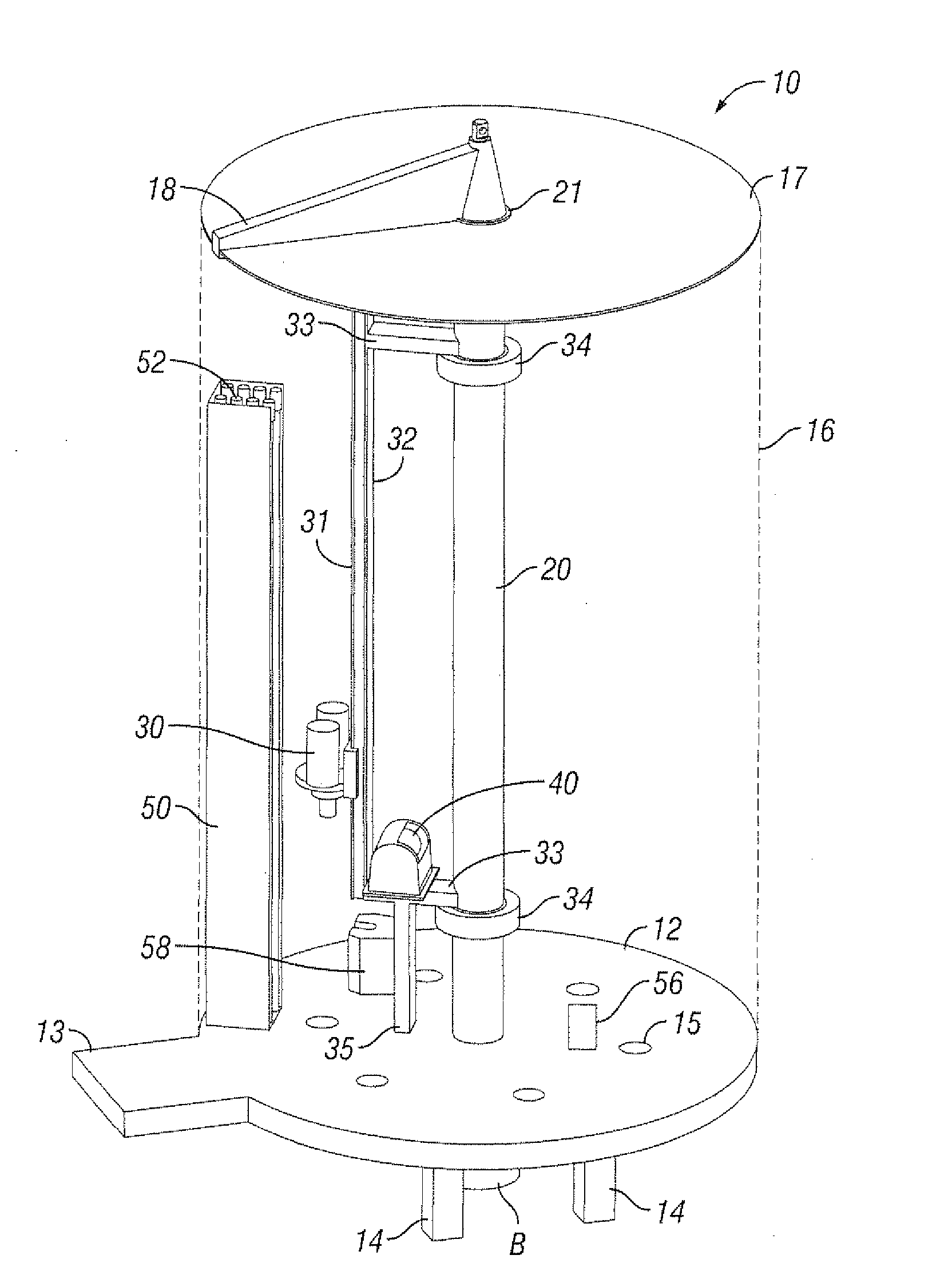
[0098]FIG. 3 shows a system 10 according to the present invention which has a base or rig floor 12 with supports 14 to which is secured an upright pillar 20. An optional shroud 16 (sides shown in dotted lines), e.g. for use in harsh weather environments, encompasses the majority of the rig floor 12 and has a top 17 A crane 18 is rotatably mounted on a top 21 of the pillar 20. A platform 13 projects from the rig floor 12.

[0099]Six holes 15 extend through rig floor 12, each hole corresponding to and above a location on the ground below the rig floor 12 where a wellbore is to be drilled and completed. Any desired number of such holes can be provided (for any desired number of wellbores).

[0100]A drilling machine 30 is movably mounted for up and down movement on a beam 31 which is part of a support 32 which is rotatably mounted on the pillar 20. Crossbeams 33 are connected to rings 34 which encompass and rotate on the pillar 20. A drawworks 40 is mounted on the lower crossbeam 33. A beam...


PUM


Abstract

A multi-function multi-hole rig is disclosed which, in certain aspects, includes multiple machines for accomplishing rig functions, e.g. drilling machine(s), tripping machine(s), casing machine(s), and / or cementing machine(s), for producing multiple usable wellbores one after the other. This abstract is provided to comply with the rules requiring an abstract which will allow a searcher or other reader to quickly ascertain the subject matter of the technical disclosure and is submitted with the understanding that it will not be used to interpret or limit the scope or meaning of the claims, 37 C.F.R. 1.72(b).

Description

CROSS-REFERENCE TO RELATED APPLICATION[0001]This application claims the benefits under the Patent Laws of U.S. Application Ser. No. 61 / 189,146 filed Aug. 15, 2008 including claiming priority therefrom and said application is incorporated fully herein by reference for all purposes.BACKGROUND OF THE INVENTION[0002]1. Field of the Invention[0003]This invention is directed to drilling oil and gas wellbores in the earth; in certain particular aspects, to drilling and completing such multiple wellbores from a single drilling rig; and, in certain particular aspects, to drilling and completing such multiple wellbores so that they are relatively close to each other.[0004]2. Description of Related Art[0005]A wide variety of drilling rigs and methods are known for drilling oil and gas wellbores in the earth. In many known systems and methods, a single wellbore is drilled with a drilling rig and then, to drill another wellbore, the drilling rig is moved to a new location, often near the drilled...

Claims


Application Information

Patent Timeline
IPC IPC(8): E21B15/00E21B43/00E21B7/00E21B44/00E21B19/00E21B23/00
CPCE21B15/003
Inventor SPRINGETT, FRANK BENJAMINREID, DAVID GILBERTMCCLUNG, III, GUY L.
Owner NAT OILWELL VARCO LP
Learn More