Apparatus and method of producing porous membranes
a porous membrane and apparatus technology, applied in the direction of membranes, filtration separation, separation processes, etc., can solve the problems of difficult cleaning, similar permanent plugging problems, and commercially unviable problems
- Summary
- Abstract
- Description
- Claims
- Application Information
AI Technical Summary
Benefits of technology
Problems solved by technology
Method used
Image
Examples
example 1
[0072]The following is a detailed description of the method of manufacture of a five layer tubular membrane using the above die head having six ports.
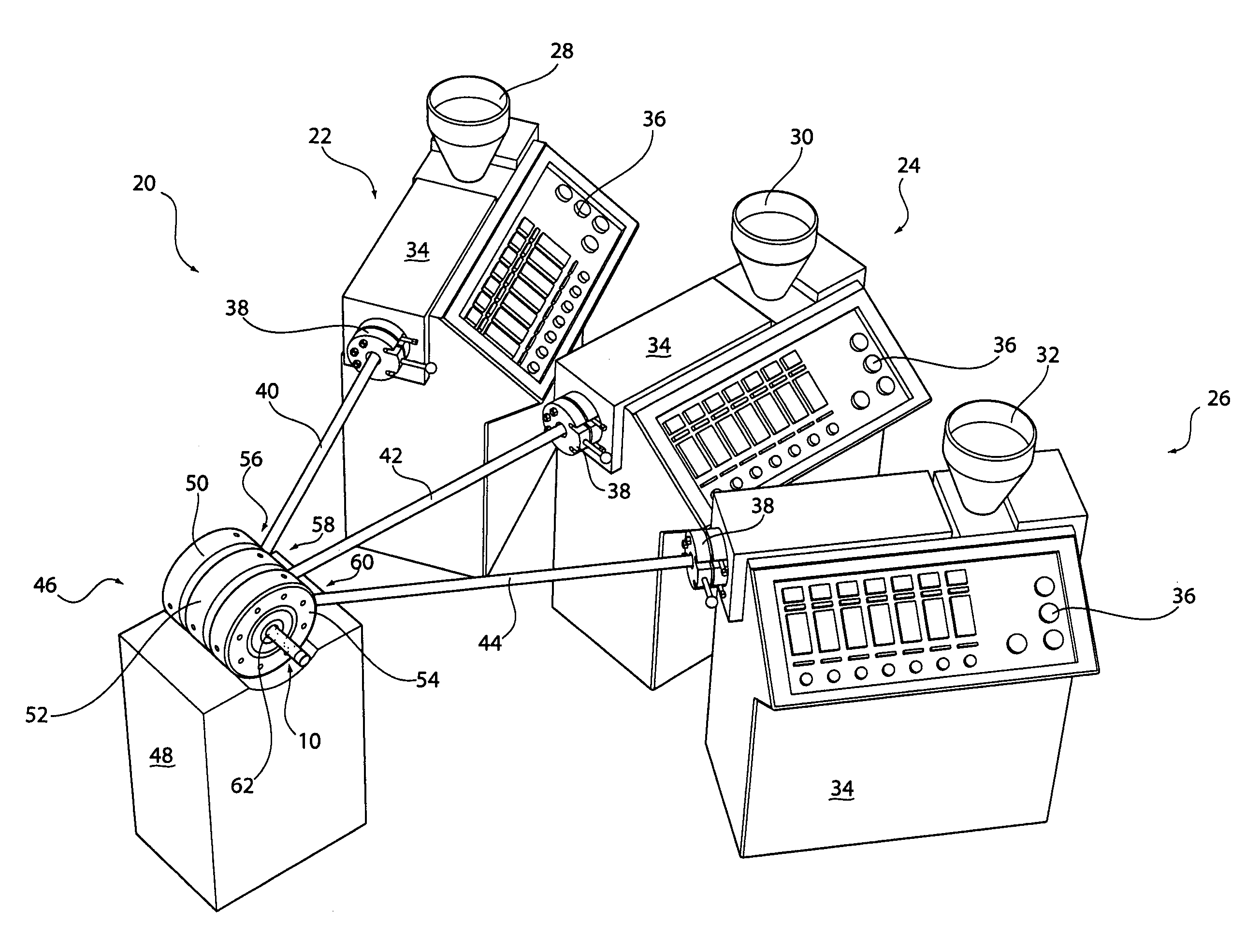
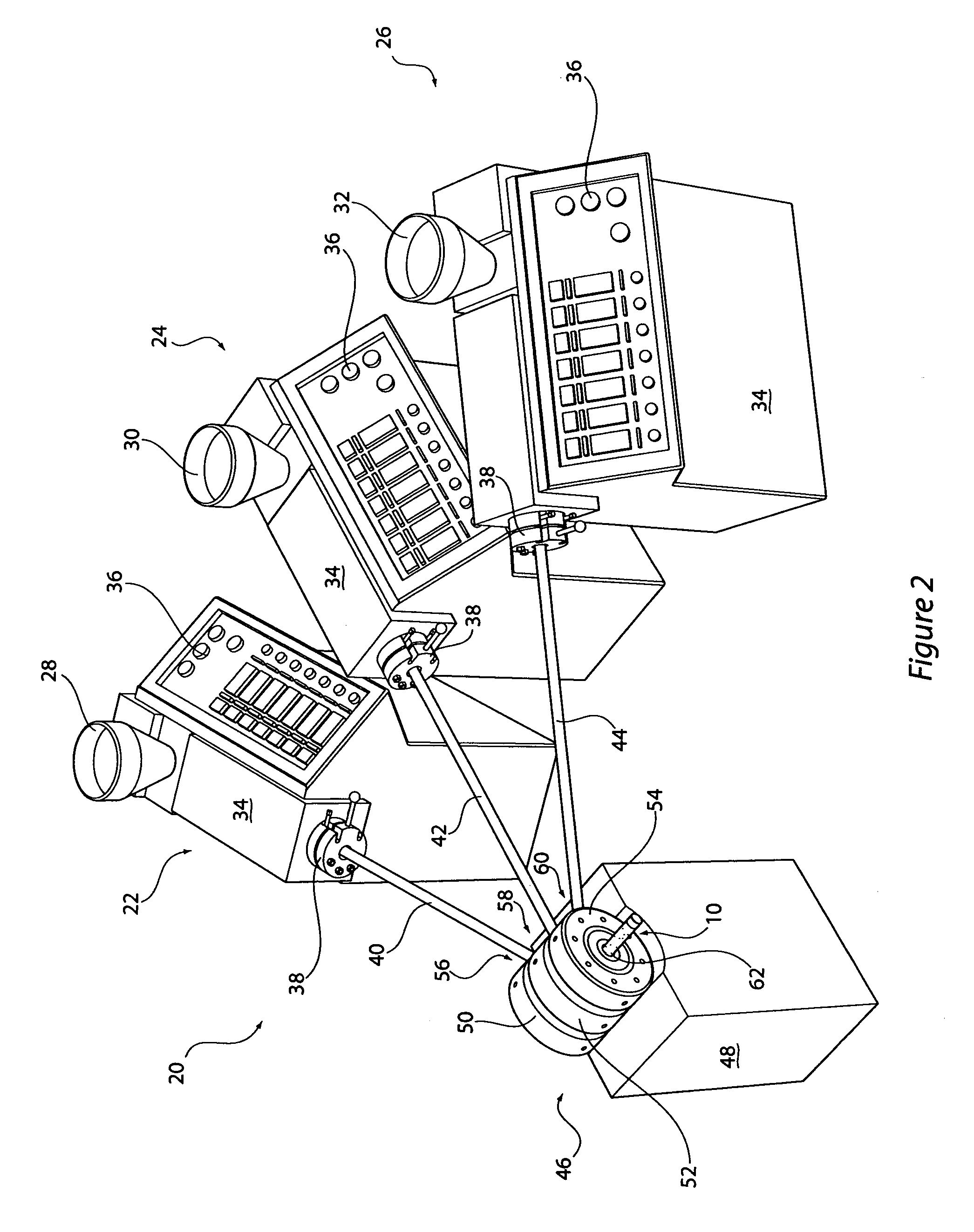
[0073]Five layers are produced using mixtures containing particles of different sizes. The following is an explanation of the mixtures that are used to produce the various layers and the ports through which they are co-extruded. Each port is supplied by an individual feed hopper with a variable pressure feed system.
[0074]Layer one is produced from a mixture extruded out through port one containing tungsten powder with a micron size between 0.1 μm to 6.0 μm preferably 0.6-1.0 μm. The powder and a binder-solvent are combined at a ratio of between 1:1 and 7:3 by volume, preferably 7:3 and processed to produce a suitable feed stock ready for use.
[0075]Layer two is produced from a mixture extruded out through port two containing stainless steel 316L powder with a micron size between 5.0 μm to 22.0 μm preferably 16.0 μm. The powder and a bin...
example 2
[0088]The following is a detailed description of the manufacture of a three layer tubular membrane using the above die head having six ports. It should be appreciated that in this example ports 4 and 5 are not used during production of the membrane.
[0089]Three layers are produced using mixtures containing particles of different sizes. The following is an explanation of the mixtures that are used to produces the various layers and the ports through which they are co-extruded. Each port is supplied by an individual feed hopper with a variable pressure feed system.
[0090]Layer one is produced from a mixture extruded out through port one containing tungsten powder with a micron size between 0.1 μm to 6.0 μm preferably 0.6-1.0 μm. The powder and a binder-solvent are combined at a ratio of between 1:1 and 7:3 by volume, preferably 7:3 and processed to produce a suitable feed stock ready for use.
[0091]Layer two is produced from a mixture extruded out through port two containing stainless st...
example 3
[0100]The following is a detailed description of the manufacture of a two layer tubular membrane using the above die head having six ports. It should be appreciated that in this example ports 3, 4 and 5 are not used during production of the membrane.
[0101]Two layers are produced using mixtures containing particles of different sizes. The following is an explanation of the mixtures that are used to produces the various layers and the ports through which they are co-extruded. Each port is supplied by an individual feed hopper with a variable pressure feed system.
[0102]Layer one is produced from a mixture extruded out through port one containing tungsten powder with a micron size between 0.1 μm to 6.0 μm preferably 0.6-1.0 μm. The powder and a binder-solvent are combined at a ratio of between 1:1 and 7:3 by volume, preferably 7:3 and processed to produce a suitable feed stock ready for use.
[0103]Layer two is produced from a mixture extruded out through port two containing stainless ste...
PUM
| Property | Measurement | Unit |
|---|---|---|
| size | aaaaa | aaaaa |
| temperatures | aaaaa | aaaaa |
| pressure | aaaaa | aaaaa |
Abstract
Description
Claims
Application Information
 - R&D
- Intellectual Property
- Life Sciences
- Materials
- Tech Scout
- Unparalleled Data Quality
- Higher Quality Content
- 60% Fewer Hallucinations
Browse by: Latest US Patents, China's latest patents, Technical Efficacy Thesaurus, Application Domain, Technology Topic, Popular Technical Reports.
© 2025 PatSnap. All rights reserved.Legal|Privacy policy|Modern Slavery Act Transparency Statement|Sitemap|About US| Contact US: help@patsnap.com


