

Hygrometer and dew-point instrument
- Summary
- Abstract
- Description
- Claims
- Application Information
AI Technical Summary
Benefits of technology
Problems solved by technology
Method used
Image

Examples
first embodiment
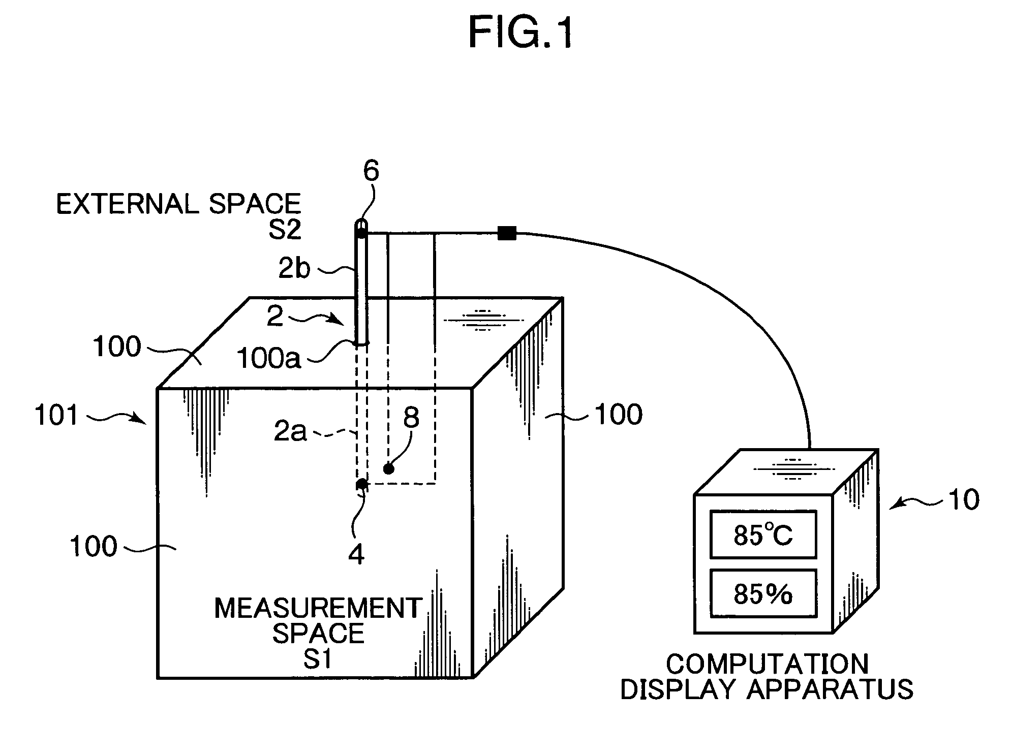
[0021]First, a hygrometer according to the first embodiment of the present invention is described with reference to FIGS. 1 and 2.
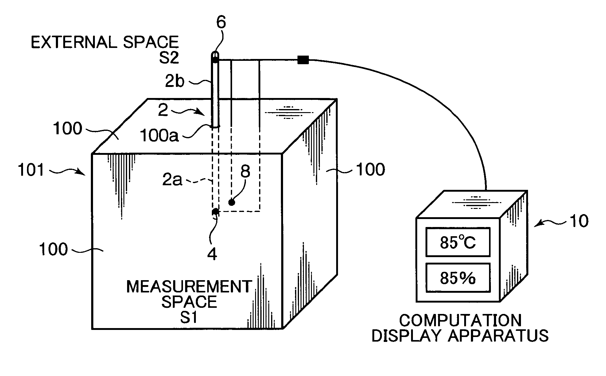
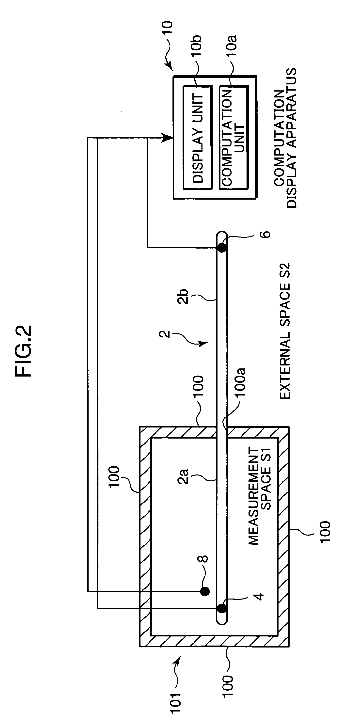
[0022]The hygrometer according to the first embodiment is for measuring a relative humidity of a measurement space S1 and has a main body part 2, a first external surface temperature sensor 4, a second external surface temperature sensor 6, a space temperature sensor 8, and computation display apparatus 10, as shown in FIG. 1.
[0023]The main body part 2 is configured by a heat pipe. The main body part 2 is configured to encapsulate therein water as a working fluid in a pressure-reduced state and to cause a heat-pipe phenomenon. The heat-pipe phenomenon here means a phenomenon in which the heat of the working fluid is transmitted as the working fluid transits from the evaporation phase to the condensation phase, by repeating evaporation and condensation of the encapsulated working fluid in a predetermined place.
[0024]The main body part 2 is disposed across ...
second embodiment
[0040]Next, the configuration of a hygrometer according to the second embodiment of the present invention is described with reference to FIG. 4.
[0041]Unlike the hygrometer according to the first embodiment described above, the hygrometer of the second embodiment is designed to forcibly cool a base side part 2d of the main body part 2 where the gaseous working fluid is condensed.
[0042]Specifically, the hygrometer according to the second embodiment has the main body part 2, the first external surface temperature sensor 4, the second external surface temperature sensor 6, the space temperature sensor 8, a peltier element 12, a connection part 14, a heat-insulating part 16, and control apparatus 18.
[0043]The functions and the configurations of the main body part 2, first external surface temperature sensor4, second external surface temperature sensor 6, and space temperature sensor 8 according to the second embodiment are the same as those of the main body part 2, first external surface...
third embodiment
[0056]Next, the configuration of a dew-point instrument according to the third embodiment of the present invention is described with reference to FIG. 5.
[0057]The dew-point instrument according to the third embodiment is for measuring the dew point of the measurement space S1, and has a configuration without the space temperature sensor 8 (see FIG. 2) of the hygrometer of the first embodiment, as shown in FIG. 5. The dew-point instrument has the same principle as the hygrometer of the first embodiment, in which the external surface temperature in the vicinity of the end part of the internal part 2a of the main body part 2 where the heat-pipe phenomenon is caused, that is, the external surface temperature of the section where the working fluid evaporates, becomes substantially equal to the dew point of the measurement space S1. The external surface temperature of the section of the internal part 2a where the working fluid evaporates is detected by the first external surface temperatu...
PUM
 Abstract
Description
Claims
Application Information