Multiplexed Lateral Flow Assay Arrays

a technology of lateral flow and arrays, applied in the field of in vitro diagnostics, can solve the problems of compromising patient safety and clinical outcomes, affecting the accuracy of assays, and wasting time, so as to increase the speed of delivery

Inactive Publication Date: 2010-02-18
PROGNOSYS
View PDF11 Cites 25 Cited by
  • Summary
  • Abstract
  • Description
  • Claims
  • Application Information

AI Technical Summary

Benefits of technology

[0014]Moreover, a single chemical capturing reagent may be applied in different titrations in the at least one analyte assay test zone, wherein at least one targeted analyte binds with the single chemical capturing reagent, and wherein a presence of the at least one targeted analyte is indicated, and is quantitatively measurable in the at least one analyte assay test zone. Furthermore, the at least one analyte assay or multiplexed analyte assay array reduces the necessary volume of the at least one test sample fluid to a minimum. Preferably, the at least one contiguous fluid flow channel conserves test sample fluid volume. Also, the at least one contiguous fluid flow channel preferably increases the speed of delivery of the at least one test sample fluid to the location of the at least one chemical capturing reagent.

Problems solved by technology

Manual entry is not only costly, but also introduces an opportunity for errors or loss of test data altogether, which, in the case of diagnostic tests, may compromise patients' safety and clinical outcomes, and in the case of food safety testing, may compromise the quality and safety of the food supply and derivative products posing great risk to public health as well as incurring significant economic costs.

Method used


Image

  • Multiplexed Lateral Flow Assay Arrays
  • Multiplexed Lateral Flow Assay Arrays
  • Multiplexed Lateral Flow Assay Arrays

Examples


Embodiment Construction

[0026]The embodiments herein and the various features and advantageous details thereof are explained more fully with reference to the non-limiting embodiments that are illustrated in the accompanying drawings and detailed in the following description. Descriptions of well-known components and processing techniques are omitted so as to not unnecessarily obscure the embodiments herein. The examples used herein are intended merely to facilitate an understanding of ways in which the embodiments herein may be practiced and to further enable those of skill in the art to practice the embodiments herein. Accordingly, the examples should not be construed as limiting the scope of the embodiments herein.

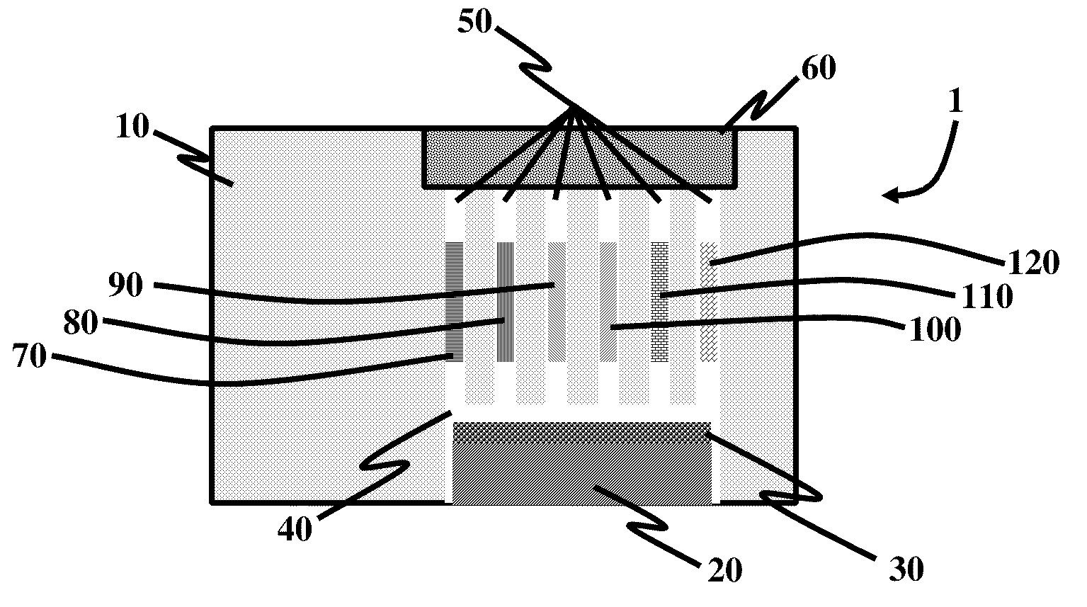
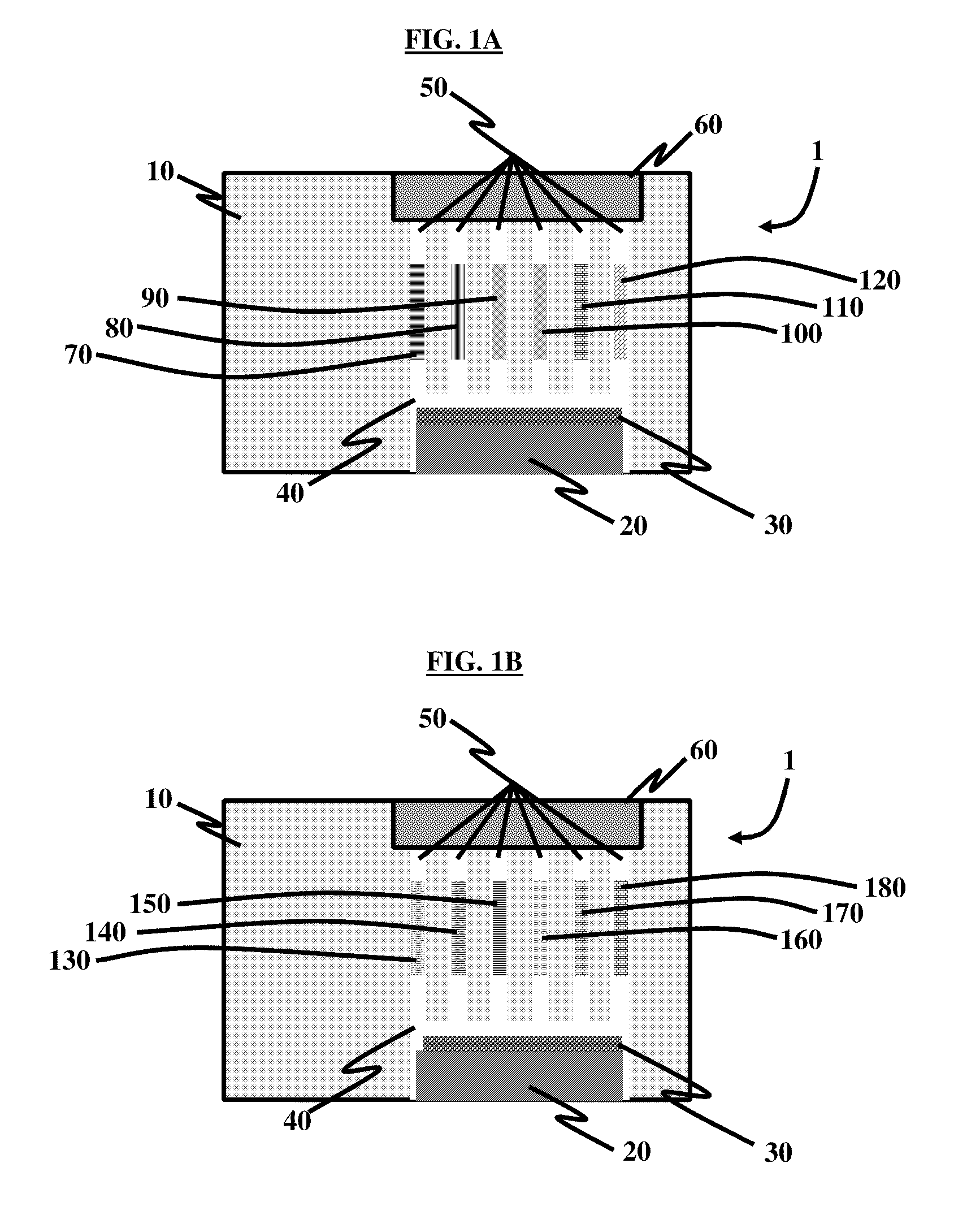
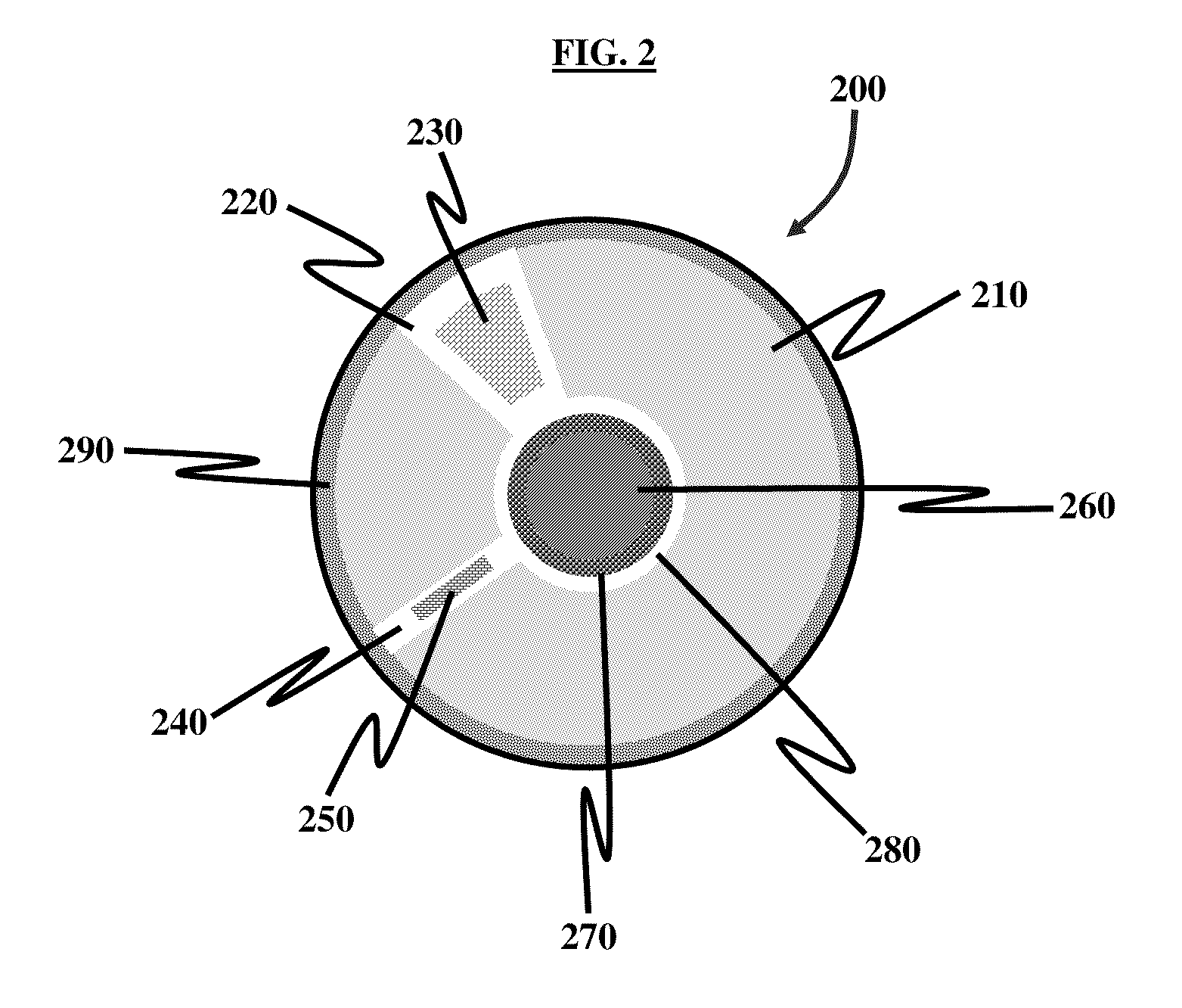
[0027]The embodiments herein provide lateral flow assays that detect any analyte and create fluid flow channels in any predefined direction within and between the reaction membranes whereby simultaneous, multiple analyte assay testing in multiplexed analyte assays and assay arrays, using one or...


PUM

PropertyMeasurementUnit
volumeaaaaaaaaaa
speedaaaaaaaaaa
hydrophilicaaaaaaaaaa

Abstract

A diagnostic test device comprising at least one membrane disposed in any of one, two, and three dimensions; at least one test sample fluid input port that receives and transfers at least one test sample fluid and onto the at least one membrane; at least one contiguous fluid flow manifold within the at least one membrane to multiplex or distribute the at least one test sample fluid; at least one contiguous fluid flow channel that operatively connects the at least one membrane to the at least one contiguous fluid flow manifold; at least one analyte assay test zone disposed within the at least one contiguous fluid flow channel; and at least one chemical capturing reagent disposed within the at least one analyte assay test zone, wherein multiple analyte assay test results are simultaneously obtained and in parallel in the diagnostic test device.

Description

CROSS-REFERENCE TO RELATED APPLICATIONS[0001]This application claims the benefit of U.S. Provisional Application Ser. No. 61 / 188,995, filed on Aug. 15, 2008, the complete disclosure of which, in its entirety, is herein incorporated by reference.BACKGROUND[0002]1. Technical Field[0003]The embodiments generally relate to the field of in vitro diagnostics, and more particularly to lateral flow assays to detect analytes.[0004]2. Description of the Related Art[0005]Traditional lateral flow assays, such as “strip” or “dip stick” tests are used for a large number of diagnostics applications. The test membranes may include, but are not limited to, glass, glass fiber, silicone, plastic, paper, aluminum foil, or other porous cellulose and rayon compounds that may be hydrophilic or hydrophobic. Specific lines or zones are “striped” onto or applied to the membrane that contain certain chemical capturing reagents or compounds, designed to react and bind with predefined biological markers which m...

Claims


Application Information

Patent Timeline
Patent Type & Authority Applications(United States)
IPC IPC(8): C40B60/12G01N33/00
CPCB01L3/5023B01L2300/0803B01L2300/0864G01N33/48771G01N33/0024G01N33/487G01N33/558G01N33/54388
Inventor COHEN, MARC H.GABRIEL, KENNETH A.LOOMIS, LAWRENCE J.
Owner PROGNOSYS
Why Eureka
Try Eureka