Method and device for detecting transmission signal with division detection

a technology of transmission signal and detection method, applied in the field of transmission signal detection method and device using division detection, can solve the problems of difficult system application, increased geometric progression of calculation, proposed methods have limitations in improving the complexity of calculation, etc., and achieve the effect of reducing the complexity of the calculation process

Inactive Publication Date: 2010-02-18
ELECTRONICS & TELECOMM RES INST
View PDF6 Cites 31 Cited by
  • Summary
  • Abstract
  • Description
  • Claims
  • Application Information

AI Technical Summary

Benefits of technology

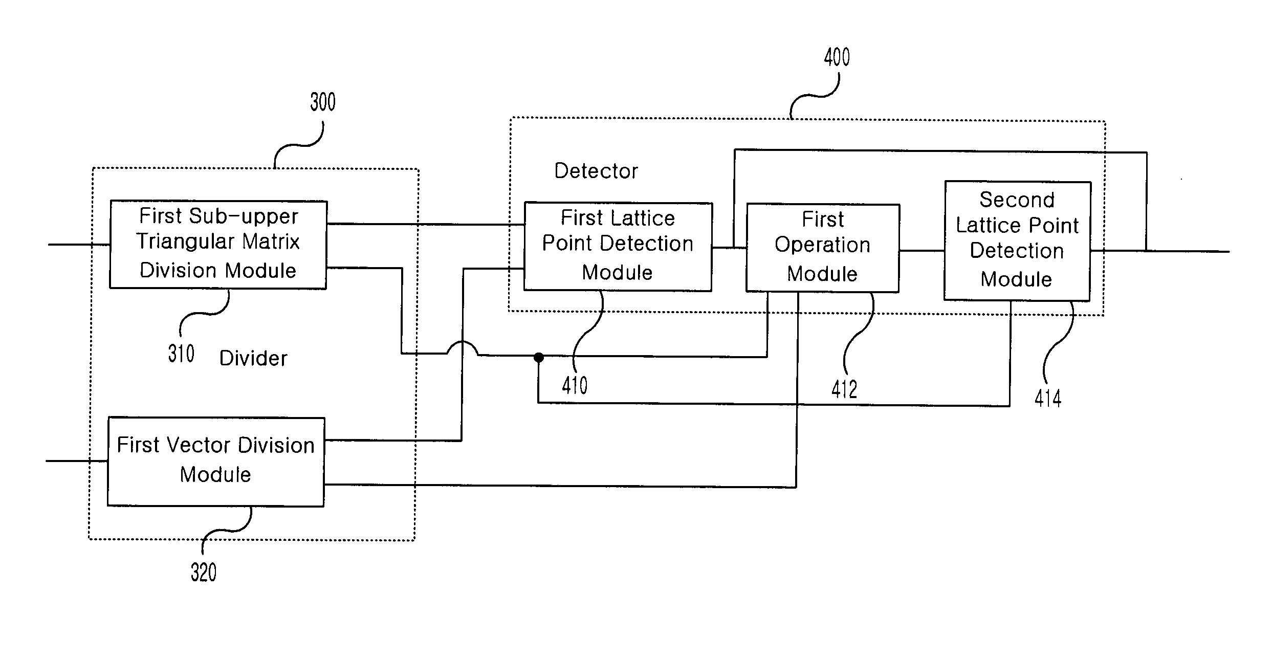
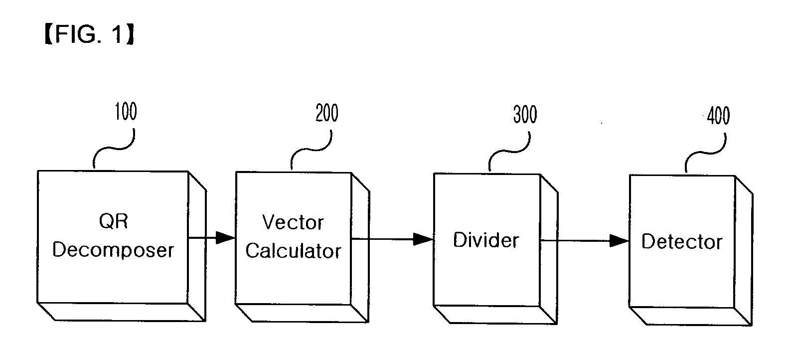
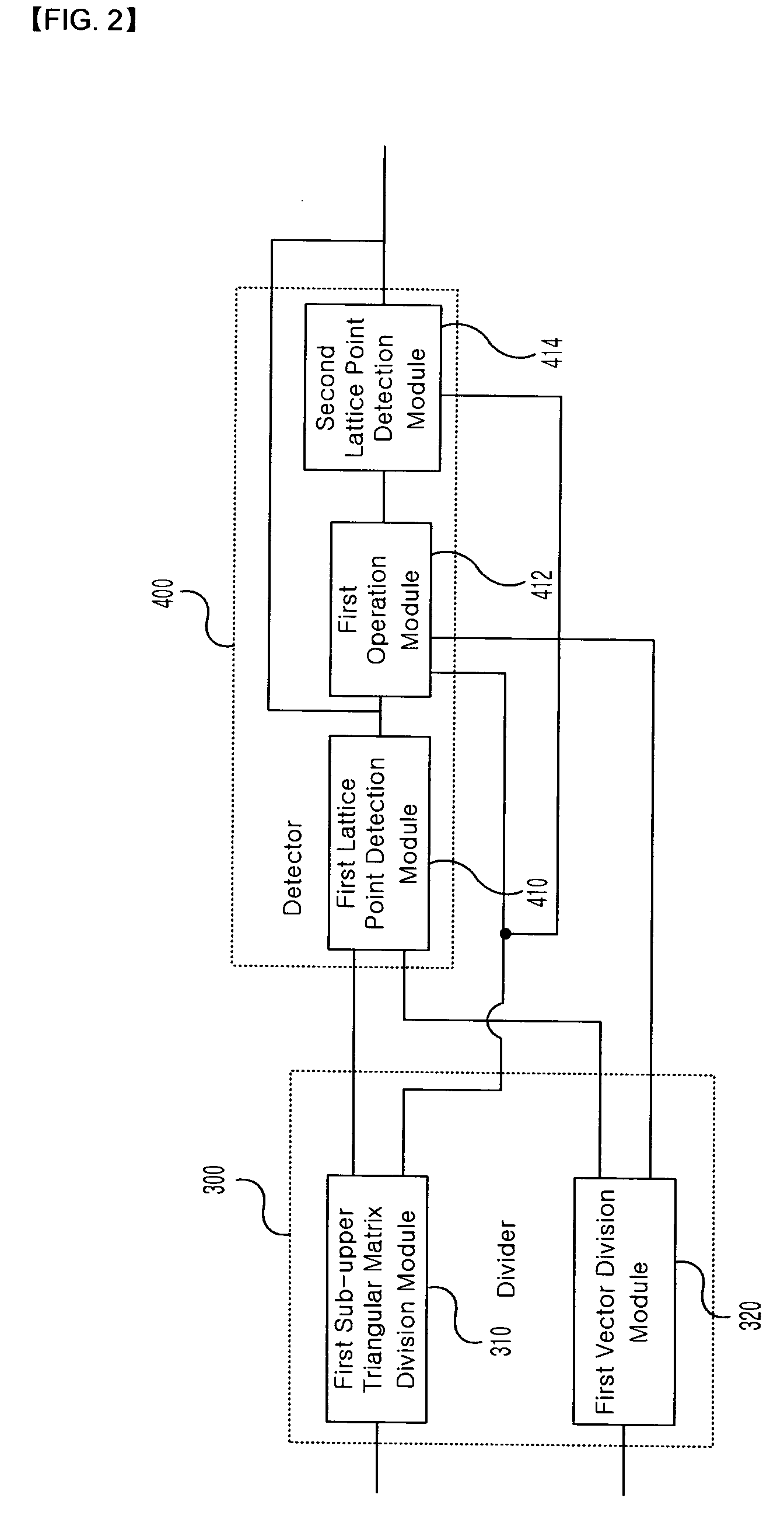
[0014]The present invention has been made in an effort to provide a method for detecting a transmission signal from a received signal and a device thereof having advantages of securing a signal detection performance equal to or higher than a predetermined level and reducing the complexity of a calculation process for simultaneous signal detection by considering an amount of calculation for a signal detection performance in a multiple input multiple output (MIMO) system.

Problems solved by technology

Therefore, when the values of M and Q become large, the amount of calculation increases in geometric progression, and there is a drawback in that it is difficult to apply to a system.
However, those proposed methods have limits in improving the complexity of the calculation when a number of signals are included in the received signal vector and the transmission signal vector.

Method used


Image

  • Method and device for detecting transmission signal with division detection
  • Method and device for detecting transmission signal with division detection
  • Method and device for detecting transmission signal with division detection

Examples


Embodiment Construction

[0035]Hereinafter, the present invention now will be described more fully with reference to the accompanying drawings, in which preferred embodiments of the invention are shown as those skilled in the art would realize. As those skilled in the art would realize, the described embodiments may be modified in various different ways, all without departing from the spirit or scope of the present invention. Further, for more apparent description of the present invention with reference to the drawings, parts that have no relationship with the description are omitted and similar parts are represented by the same reference numerals through the specification.

[0036]In addition, a part that includes a constituent element means that the part may further include other constituent elements rather than only the constituent element.

[0037]Further, the term “module” described in this specification means one unit that processes a specific function or an operation and may be implemented by hardware, sof...


PUM


Abstract

The present invention relates to a method and device for detecting a transmission signal on the basis of a received signal by applying a division and detection algorithm. An embodiment of the invention provides a method of detecting a transmission signal including: obtaining a unitary matrix and an upper triangular matrix by performing a sorted QR-decomposition algorithm with respect to a matrix indicating a channel state; calculating a vector y by multiplying a transpose matrix of the unitary matrix by the received signal Y; dividing the upper triangular matrix R into a plurality of sub-upper triangular matrices and dividing the calculated vector y into a plurality of sub-vectors so as to correspond to the divided plurality of sub-upper triangular matrices; and detecting a lattice point corresponding to each of the divided sub-vectors using the divided plurality of sub-upper triangular matrices.

Description

BACKGROUND OF THE INVENTION[0001](a) Field of the Invention[0002]The present invention relates to a transmission signal detection method and device using division detection. In particular, the present invention relates to an adaptive transmission signal detection method and device that are capable of sufficiently reducing error probability of a detected signal and simultaneously reducing an amount of calculation when a transmission signal vector is detected from a received signal vector corresponding to a transmission signal vector that includes a plurality of signals and uses high modulation, and the number of signals included in the received signal vector and the transmission signal vector is large.[0003](b) Description of the Related Art[0004]A receiving terminal of a communication system detects a transmission signal vector X having M complex numbers from a signal vector Y having N complex numbers measured in the receiving terminal, wherein the transmission signal vector X shoul...

Claims


Application Information

Patent Timeline
Patent Type & Authority Applications(United States)
IPC IPC(8): G06F17/16
CPCH04B7/0413H04L25/03171H04L25/0246H04L25/0204
Inventor PARK, IN-SOOKJEONG, BYUNG-JANGCHUNG, HYUN-KYU
Owner ELECTRONICS & TELECOMM RES INST
Why Eureka
Try Eureka