System and method for ultrasonic examination of threaded surfaces

a technology of ultrasonic examination and threaded surfaces, which is applied in the direction of instruments, diagnostic recording/measuring, diagnostics, etc., can solve the problems of inability to examine the end or mounting thread, laborious and general-purpose procedures, and inability to remove the gas cylinder from the tube trailer and the mounting, so as to improve the alignment of the probe and optimize the signal used

Inactive Publication Date: 2010-02-25
PRAXAIR TECH INC
View PDF0 Cites 2 Cited by
  • Summary
  • Abstract
  • Description
  • Claims
  • Application Information

AI Technical Summary

Benefits of technology

[0007]In another aspect, the present invention may be characterized as an ultrasonic test instrument for examining threaded test objects or examination articles. The present ultrasonic test instrument comprises: a probe having one or more transducers with a piezoelectric crystal for transmission and reception of ultrasonic signals; a wear plate disposed adjacent to the ultrasonic transducer(s) and piezoelectric crystal to protect the ultrasonic transducer(s) piezoelectric crystal from abrasion; and a shoe disposed around the probe and wear plate. Particular features of the present ultrasonic test instrument include a thread-like exterior surface on the shoe adapted to mate with the threaded surface of the test object or examination article. The probe further includes a narrow window in the thread-like exterior surface of the shoe wherein the shoe absorbs the ultrasonic pulse energy transmitted from the transducer(s) except for the energy passing through the narrow window. Another useful feature of the present probe is that the wear plate is preferably contoured in the shape of a lens to focus the energy and localize the contact between the wear plate and the peak of the thread through which the ultrasonic waves will pass into the examination article. Such localized contact improves the alignment of the probe with the examination article and optimizes the signals used during the test procedures.

Problems solved by technology

Such current methods are labor intensive and generally expensive procedures.
However, removal of the gas cylinder from the tube trailer and removal of the mounting is still required.
It is not capable of examining the end or mounting threads.

Method used


Image

  • System and method for ultrasonic examination of threaded surfaces
  • System and method for ultrasonic examination of threaded surfaces
  • System and method for ultrasonic examination of threaded surfaces

Examples


Embodiment Construction

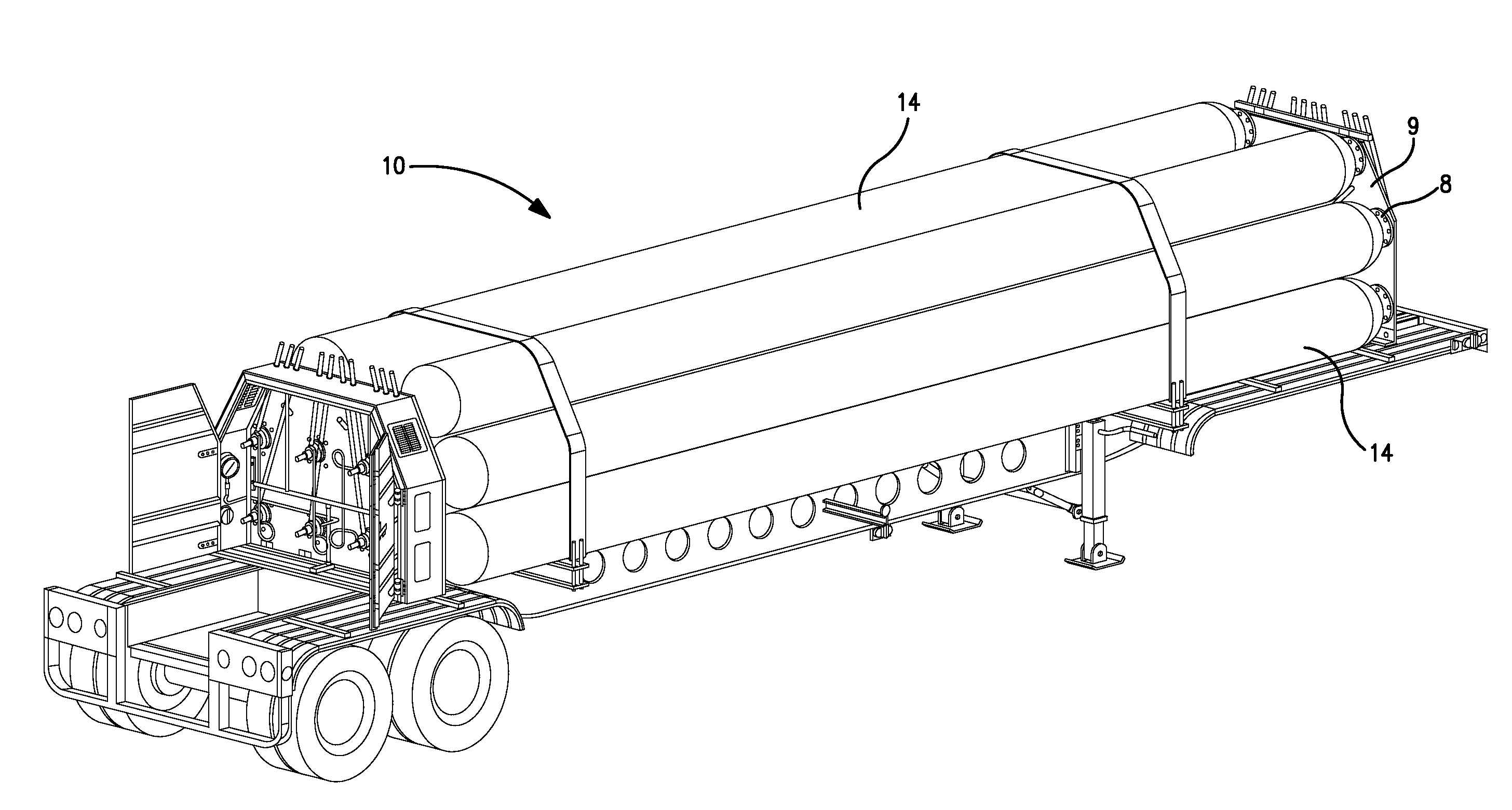
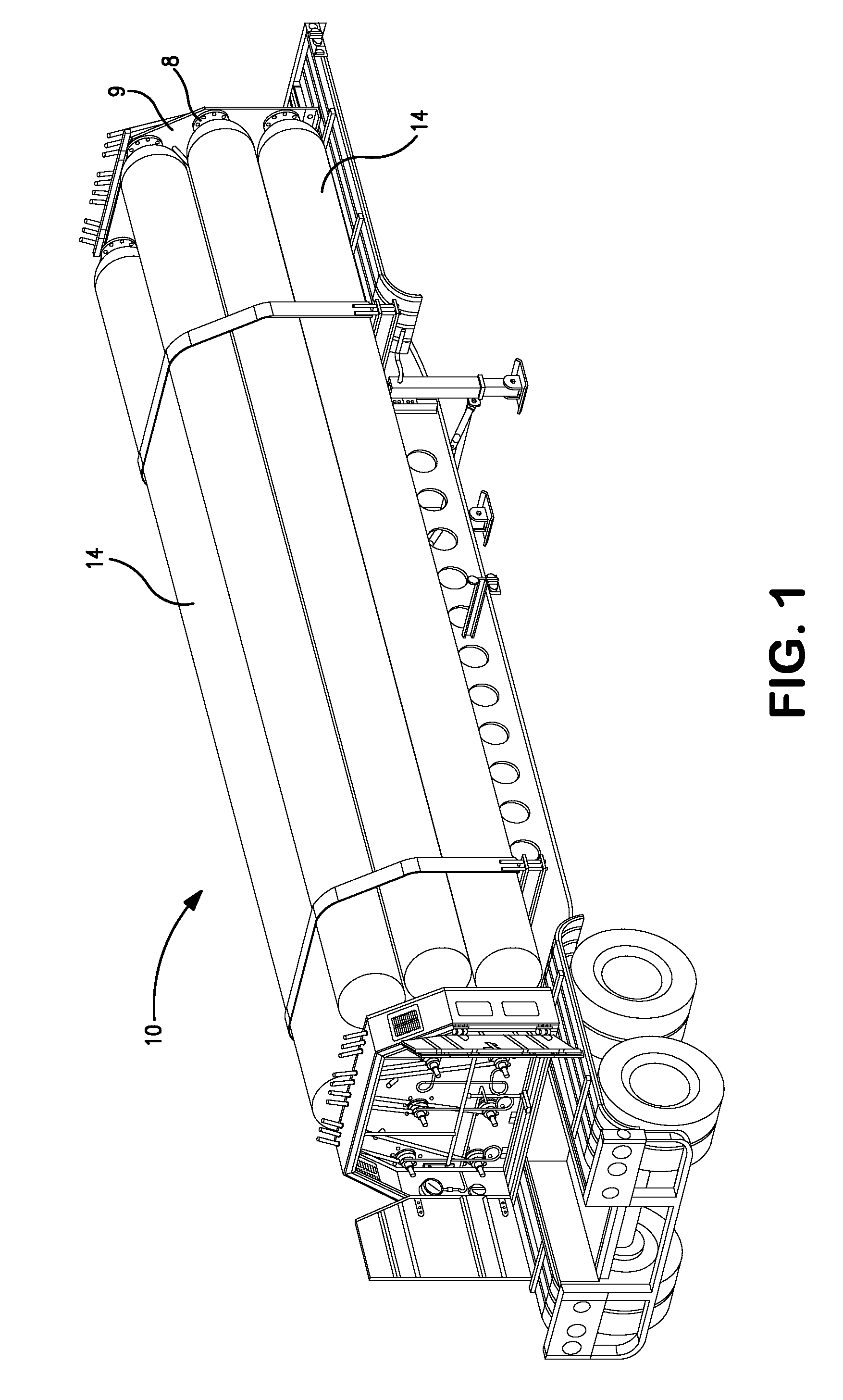
[0013]Turning now to the Figures, there are shown illustrations of a tube trailer together with the present probe for ultrasonic examination of mounting threads. More particularly, FIGS. 1 through 3 present illustrations of the typical structural arrangement of compressed gas cylinder tube trailers as well as the probe as it is used during examination of the mounting threads of the type typically found on such compressed gas cylinder tube trailers.

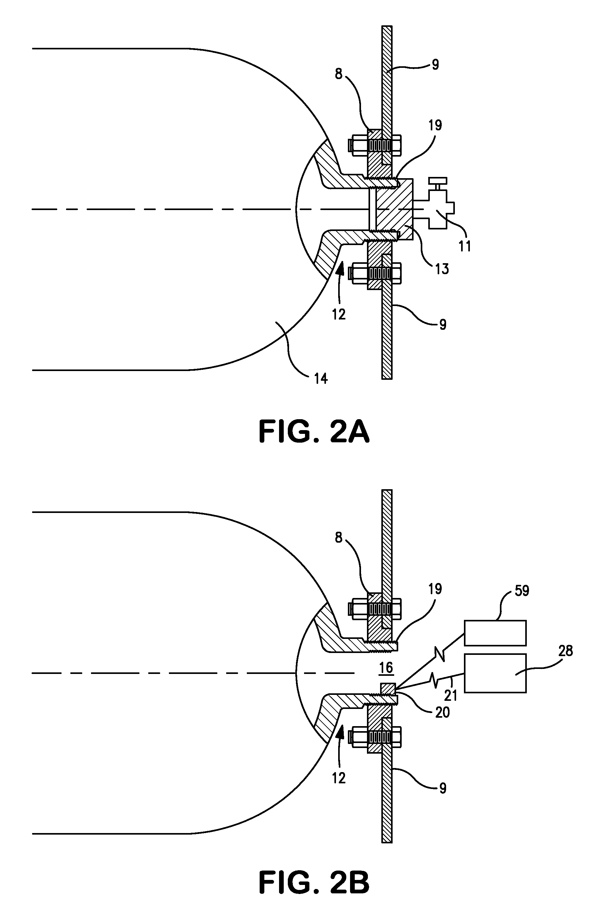
[0014]Utilizing the illustrated embodiment of the probe 20, the preferred method for inspecting mounting threads 19 on a tube 14 affixed via a mounting flange 8 to a bulkhead 9 of tube trailer 10 is accomplished without removing the tube from the tube trailer 10. The preferred method involves first removing the tube valve 11 and an end plug 13 from an end or neck 12 of the tube 14 to define an opening 16 on the neck 12 exposing an interior surface 17. The next step involves inserting the probe 20 into the opening 16 and placing it in direc...


PUM

PropertyMeasurementUnit
frequencyaaaaaaaaaa
ultrasonic inspectionaaaaaaaaaa
areaaaaaaaaaaa

Abstract

A system and method for ultrasonic examination of a threaded test object, and more particularly, the mounting threads of a compressed gas tube while the tube is affixed to a tube trailer is provided. The disclosed ultrasonic test instrument includes a probe having one or more transducers for transmission and reception of ultrasound pulses, a contoured wear plate, and a shoe of highly attentuative material having a thread-like exterior surface adapted to mate with the threaded surface of the test object. The shoe further includes a narrow window in the thread-like exterior surface such that the shoe absorbs most of the ultrasonic pulses transmitted from the piezoelectric crystal except for the ultrasonic transmissions passing through the narrow window to the test object.

Description

FIELD OF THE INVENTION[0001]The present invention relates to ultrasonic examination of threaded surfaces, and more particularly to in-situ ultrasonic examination or inspection of mounting threads of a tube while the tube is affixed to a tube trailer.BACKGROUND[0002]The United States Department of Transportation requires periodic inspection of tube mounting threads on tube trailers used to transport compressed gases. In accordance with the current inspection procedure, to prevent the wear on the mounting threads of a tube from weakening the threaded connection to a point where safety may be compromised, the mounting threads on the tube must be inspected once every 10 years. The required inspection is a visual inspection using a Thread Pitch Gauge for measurement of the thread wear. Such visual inspection, however, requires removal of the mounting flanges. When evaluating the mounting threads on tubes, there are two basic categories of thread degradation that should be considered: gen...

Claims


Application Information

Patent Timeline
Patent Type & Authority Applications(United States)
IPC IPC(8): G01N29/00
CPCG01N29/07G01N29/2437G01N2291/2691G01N2291/2636G01N29/28
Inventor MITCHELL, JAMES R.
Owner PRAXAIR TECH INC
Why Eureka
Try Eureka