Particle-Based Microfluidic Device for Providing High Magnetic Field Gradients

a microfluidic device and magnetic field gradient technology, applied in the field of microfluidic devices, can solve the problems of difficult generation of high magnetic field gradients in micro total analysis systems (tas) and inability to provide continuous separation

Inactive Publication Date: 2010-02-25
RGT UNIV OF CALIFORNIA
View PDF3 Cites 59 Cited by
  • Summary
  • Abstract
  • Description
  • Claims
  • Application Information

AI Technical Summary

Problems solved by technology

Unlike macro-scale devices, high magnetic field gradients in Micro Total Analysis Systems (μTAS) are difficult to generate.
Although these platforms can easily manipulate the magnetic beads in batches, they do not provide a continuous separation.

Method used


Image

  • Particle-Based Microfluidic Device for Providing High Magnetic Field Gradients
  • Particle-Based Microfluidic Device for Providing High Magnetic Field Gradients
  • Particle-Based Microfluidic Device for Providing High Magnetic Field Gradients

Examples


examples

Material and Methods

[0042]Channel fabrication

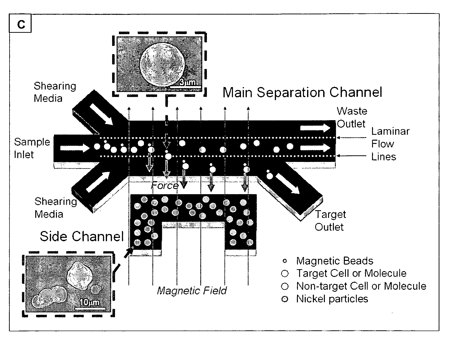
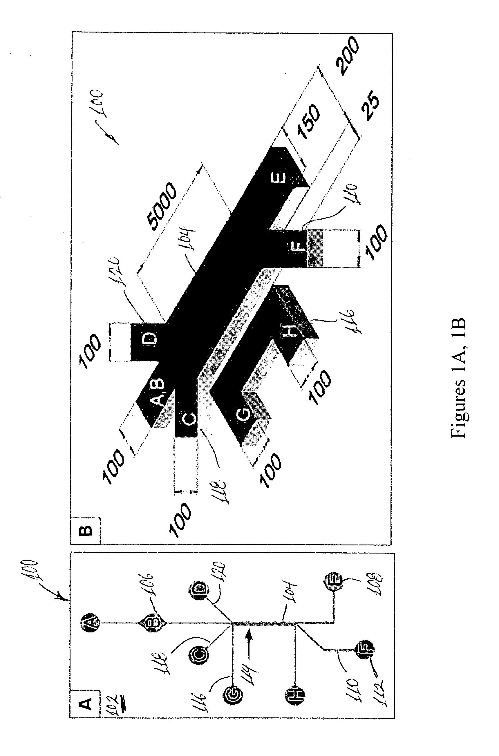
[0043]Different channel geometries were designed in conventional computer-aided design software and printed out onto a negative transparency mask (PHOTOPLOT, CO). The channels were fabricated using replicate molding techniques. The mold was fabricated using SU-8 negative photoresist (MICROCHEM, MA) on a silicon wafer. The thickness of the mold was ˜50 μm. Then, a polydimethylsiloxane mixture (PDMS), at a composition of 1 to 10 (weight ratio of curing agent to PDMS), was poured onto the mold and subsequently cured at 60° C. for 4 hours. After the curing process, the PDMS replicate was peeled off and punched with inlets and outlets at designated locations. To complete the fabrication procedures, both the PDMS channel surface and a glass substrate were activated by oxygen plasma in order to bond the two surfaces together (see FIGS. 1A and 1B).

[0044]All inlets and outlets are 100 μm in width with the exception of outlet E, which is 150 μm. Th...


PUM

PropertyMeasurementUnit
magnetic susceptibilityaaaaaaaaaa
concentrationaaaaaaaaaa
magnetic fieldaaaaaaaaaa

Abstract

A microfluidic device for manipulating particles in a fluid has a device body that defines a main channel therein, in which the main channel has an inlet and an outlet. The device body further defines a particulate diverting channel therein, the particulate diverting channel being in fluid connection with the main channel between the inlet and the outlet of the main channel and having a particulate outlet. The microfluidic device also has a plurality of microparticles arranged proximate or in the main channel between the inlet of the main channel and the fluid connection of the particulate diverting channel to the main channel. The plurality of microparticles each comprises a material in a composition thereof having a magnetic susceptibility suitable to cause concentration of magnetic field lines of an applied magnetic field while in operation. A microfluidic particle-manipulation system has a microfluidic particle-manipulation device and a magnet disposed proximate the microfluidic particle-manipulation device.

Description

CROSS-REFERENCE TO RELATED APPLICATION[0001]This application claims priority to U.S. Provisional Application No. 60 / 907,501 filed Apr. 5, 2007, the entire contents of which are hereby incorporated by reference.[0002]This invention was made with Government support under NIH Grant No. DK070328 and NASA Award NCC2-1364. The Government may have certain rights in this invention.BACKGROUND[0003]1. Field of Invention[0004]This application relates to microfluidic devices, and more particularly microfluidic devices that can be used to generate high magnetic field gradients in microfluidic channels.[0005]2. Discussion of Related Art[0006]The contents of all references, including articles, published patent applications and patents referred to anywhere in this specification are hereby incorporated by reference.[0007]Many cell or bio-particle separation or concentration techniques require large electric or magnetic field gradients, such as dielectrophoresis (see, e.g., R. Krupke, F. Hennrich, H....

Claims


Application Information

Patent Timeline
Patent Type & Authority Applications(United States)
IPC IPC(8): B01D43/00
CPCB01L3/502761B01L3/502776B01L2200/0652B03C2201/18B03C1/01B03C1/288B01L2400/043B03C2201/26
Inventor LIN, ADAM YUHWONG, TAK SING
Owner RGT UNIV OF CALIFORNIA
Why Eureka
Try Eureka