Seamless control of spring stiffness in a liquid spring system

a liquid spring and stiffness technology, applied in the field of vibration control systems, can solve problems such as destructive force of vibration

Inactive Publication Date: 2010-02-25
LIQUIDSPRING TECH
View PDF50 Cites 33 Cited by
  • Summary
  • Abstract
  • Description
  • Claims
  • Application Information

AI Technical Summary

Benefits of technology

[0010]In an additional embodiment, a mode selection switch is electrically coupled to the controller. The mode selection switch producing a signal indicative of desired suspension performance. In an embodiment, the selection switch allows for the selection of three settings of varying ride and handling character. The controller may further alter the pulse width in response to the mode selection switch signal.

Problems solved by technology

Vibration is a destructive force in a variety of environments.

Method used


Image

  • Seamless control of spring stiffness in a liquid spring system
  • Seamless control of spring stiffness in a liquid spring system
  • Seamless control of spring stiffness in a liquid spring system

Examples


Embodiment Construction

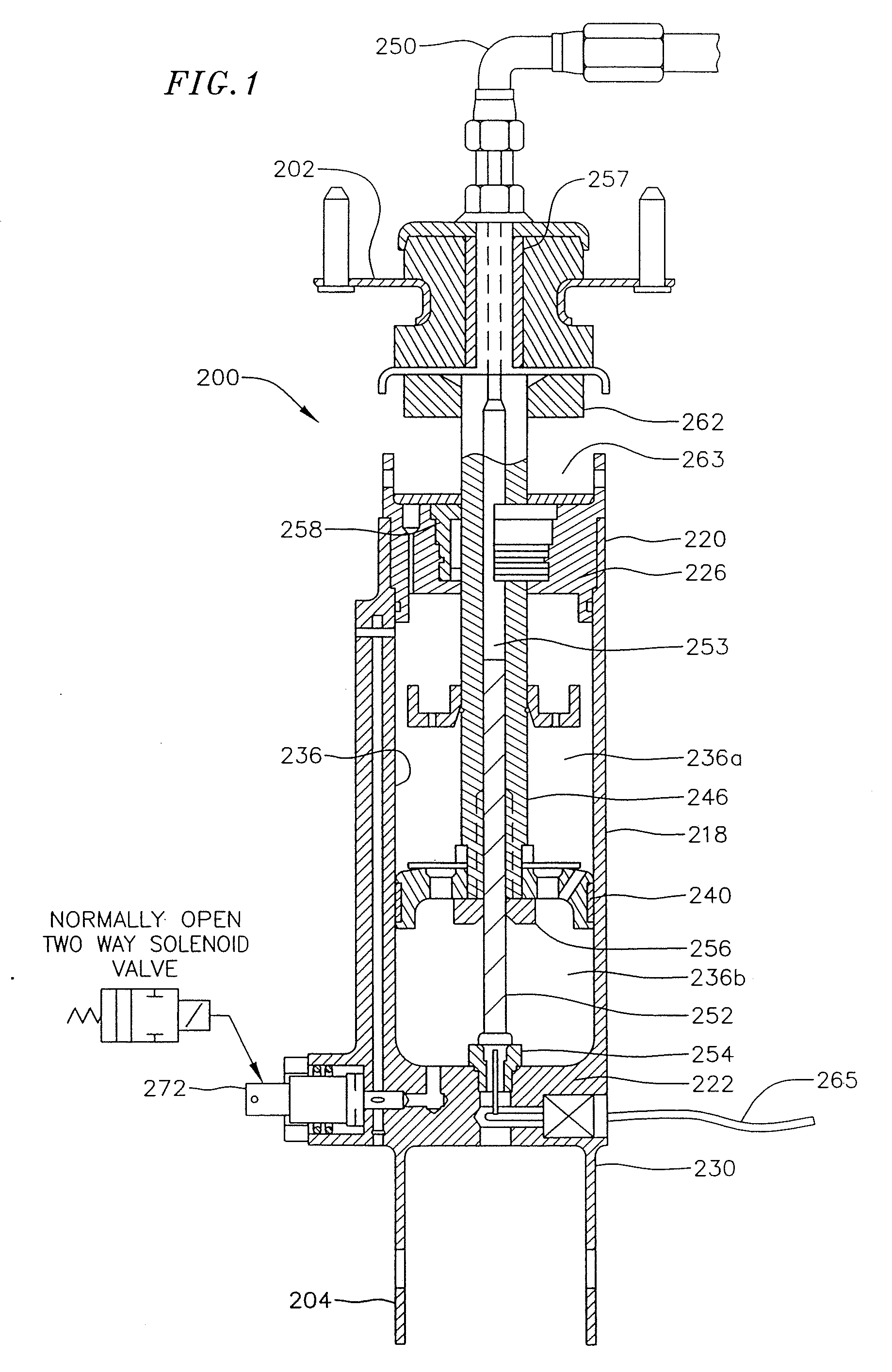
[0042]Schematically illustrated in FIG. 1 is a partially cross-sectional illustration of an adjustable liquid spring device, indicated generally at 200, which embodies principles of the present invention. Liquid spring 200 comprises a generally vertically oriented, single rod end type liquid spring. The present invention also comprehends the use of a double rod end type liquid spring as described in U.S. application Ser. No. 927,795 and incorporated herein by reference. The liquid spring 200 is connected by its upper end mounting bracket 202 to the vehicle frame (not shown), and by its lower end mounting bracket 204 to the support structure (not shown) of its associated wheel, and operates to provide the requisite suspension system spring and damping forces at its associated wheel location.

[0043]Liquid spring 200 includes an elongated, generally vertically oriented tubular housing 218 having an upper end 220 and a lower end 222. An upper annular gland member 226 is threaded into the...


PUM


Abstract

A vibration control system for a structure having a first structural member and a second structural member. The vibration control system having a liquid spring operably interposed between the first structural member and the second structural member. The liquid spring uses a compressible liquid to seamlessly generate spring and / or damping forces in the suspension system in response to relative displacement between the first structural member and the second structural member. A second volume of compressible liquid is located in a second chamber. The second volume is removably connected to the liquid spring by a fluid passage. A valve is coupled to the fluid passage, the valve selectively operable to place the second volume in communication with the liquid spring. A controller is electrically coupled to the valve. The controller emitting a control signal to control the valve.

Description

CROSS-REFERENCE TO RELATED APPLICATION(S)[0001]This application is a Continuation of U.S. patent application Ser. No. 10 / 493,557, filed Apr. 23, 2004 which claims priority to and the benefit of International Application No. PCT / US02 / 31230 filed on Sep. 30, 2002, which claims priority to and the benefit of U.S. patent application Ser. No. 10 / 001,128 filed Oct. 23, 2001, now issued as U.S. Pat. No. 6,679,504 the entire contents being incorporated herein by reference.FIELD OF THE INVENTION[0002]The present invention relates to vibration control systems and, more particularly, to a system and method for seamlessly controlling the stiffness and damping of a liquid spring vibration control system using a controlled valve.BACKGROUND OF THE INVENTION[0003]Vibration is a destructive force in a variety of environments. Vibration can be periodic, as created by a rotating compressor in an air conditioning unit or an engine in a car. Periodic vibration is characterized by a particular frequency ...

Claims


Application Information

Patent Timeline
Patent Type & Authority Applications(United States)
IPC IPC(8): B60G17/015B60G17/019B60G17/04E04H9/02F16F5/00F16F9/10F16F15/02
CPCF16F5/00B60G17/0432
Inventor DELORENZIS, DAMONMEYER, RICHARD J.
Owner LIQUIDSPRING TECH
Why Eureka
Try Eureka