Multibeam doubly convergent electron gun

a double-convergent electron gun and beamlet technology, applied in the field of microwave, millimeter and sub millimeter wavelength generation, amplification and processing arts, can solve problems such as unsatisfactory, and achieve the effect of reducing the radius of each beaml

Inactive Publication Date: 2010-02-25
MANHATTAN TECH LTD
View PDF21 Cites 13 Cited by
  • Summary
  • Abstract
  • Description
  • Claims
  • Application Information

AI Technical Summary

Benefits of technology

[0007]In one aspect, an electron gun includes a focus electrode that surrounds two or more cathodes, wherein each cathode emits a beamlet comprised of a plurality of electrons directed to a predetermined location. A first anode receives each beamlet at the predeter...

Problems solved by technology

For higher frequency operation, however, this is not satisfactory because ...

Method used


Image

  • Multibeam doubly convergent electron gun
  • Multibeam doubly convergent electron gun
  • Multibeam doubly convergent electron gun

Examples


Embodiment Construction

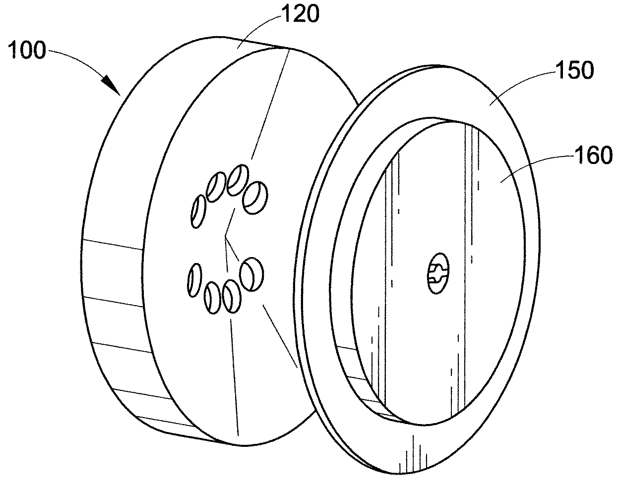
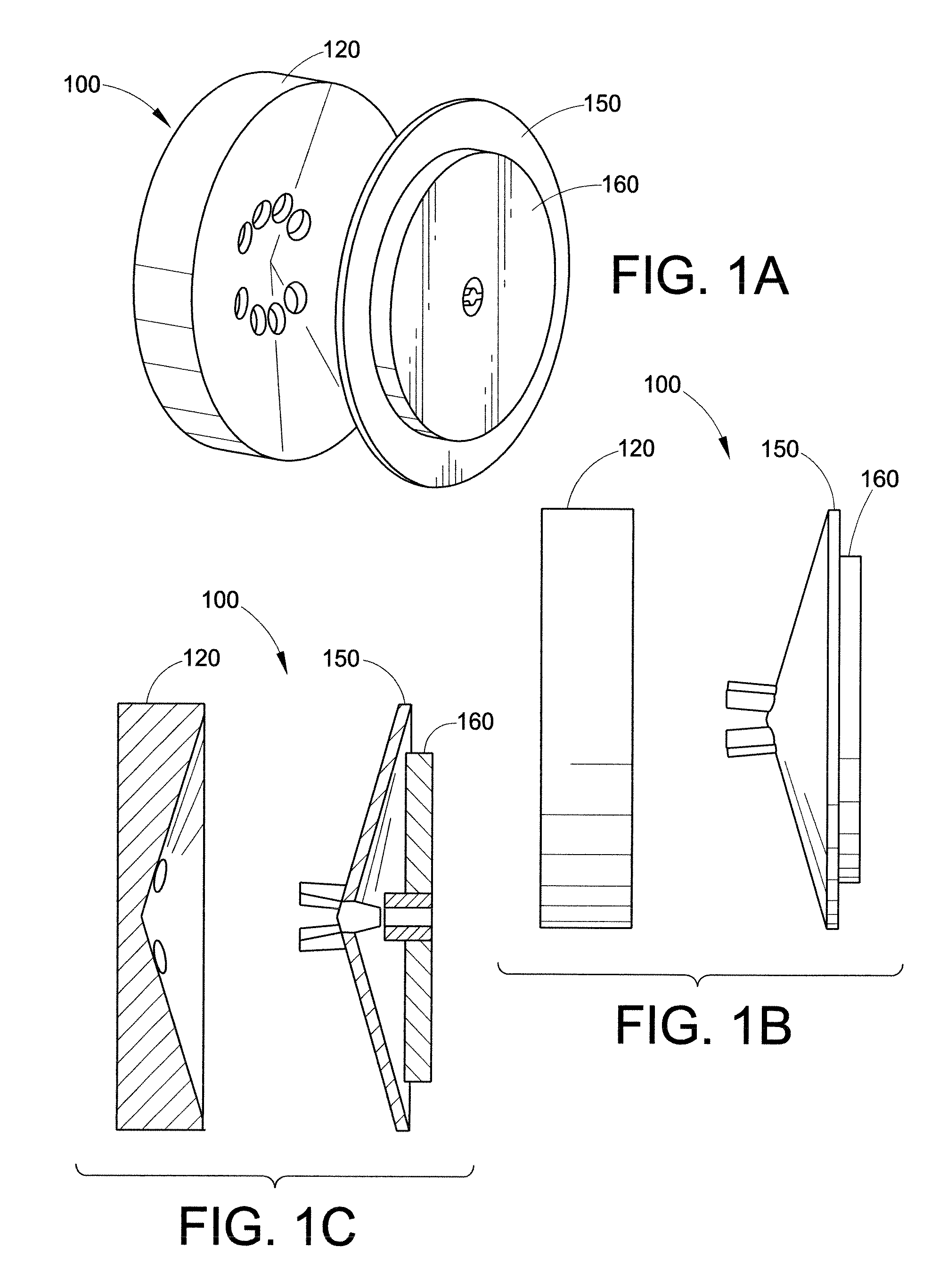
[0034]The operation of a typical vacuum electron device (VED) requires an electron beam to pass through an interaction region such as a slow wave circuit in order to produce the desired amplification or oscillation. Generally, the current density required is greater than what is practical to achieve with a thermionic cathode. To achieve a suitable current for operation of the VED, an electron gun is used to compress the beam of electrons emitted from the cathode to operate the VED. In some instances, for operation at lower frequency, the current carried by a single electron beam is not sufficient to operate the VED at the desired beam voltage. In these instances, it may be possible to use an array of singly convergent electron beams to achieve the desired current. The electron gun design problem is further exacerbated for operation at higher frequencies where the dimensions of the interaction region are greatly reduced, corresponding to the shorter wavelengths, and the electron beam...


PUM


Abstract

This disclosure describes a multibeam doubly convergent electron gun. Two or more beamlets can be run parallel to the axis at a prescribed radius to produce sufficient current to drive the VED. In order to obtain sufficient cathode surface area to provide the required current, the beamlets are launched from a cathode radius greater than the radius required in a slow wave circuit. In one embodiment, an electron gun includes a focus electrode that surrounds two or more cathodes, wherein each cathode emits a beamlet comprised of a plurality of electrons directed to a predetermined location. A first anode receives each beamlet at the predetermined location, accelerates each beamlet and changes the radius of each beamlet. A second anode receives each beamlet from the first anode, directs each beamlet along a predetermined axis, further accelerates, and can further compress each beamlet.

Description

PRIORITY[0001]This application claims the priority of provisional application 61 / 090,285, filed Aug. 20, 2008.RIGHTS IN INVENTION[0002]This project was funded in part by U.S. Government contracts FA9550-07-C-0076 and W911NF-06-C-0086. Therefore, the United States government may own certain rights to this invention.BACKGROUND[0003]The present exemplary embodiment relates to microwave, millimeter and sub millimeter wavelength generation, amplification and processing arts. It finds particular application in conjunction with electron devices, and will be described with particular reference thereto. It is to be appreciated, however, that the present exemplary embodiment is also amenable to other like applications.[0004]Vacuum electron devices, such as a traveling wave tube (TWT), a klystron, and a backward wave oscillator (BWO), are commonly used as amplifiers of electromagnetic signals or as sources of electromagnetic energy for applications that require operation at high frequency or h...

Claims


Application Information

Patent Timeline
IPC IPC(8): H01J29/51
CPCH01J23/04H01J25/34H01J23/06
Inventor DAYTON, JR., JAMES A.KORY, CAROL L.
Owner MANHATTAN TECH LTD
Why Eureka
Try Eureka