Light emitting module, lighting device and display device

a technology light emitting modules, which is applied in the direction of semiconductor devices for light sources, light and heating apparatus, planar light sources, etc., can solve the problems of insufficient heat dissipation properties and heat generated by light emitting units, and achieve the effect of improving the heat dissipation properties of light emitting modules

Active Publication Date: 2010-02-25
SATCO PRODS
View PDF11 Cites 36 Cited by
  • Summary
  • Abstract
  • Description
  • Claims
  • Application Information

AI Technical Summary

Benefits of technology

[0015]When the light emitting module of the present invention is mounted on a heatsink with, for example, the light emitting unit on the insulating plate at the front side, the part (or the vicinity thereof) of the heat conducting plate that is hottest during light emission contacts the heatsink, and therefore the heat that occurs during light emission is effective conveyed via the heat conducting plate to the heatsink. This improves heat dissipation properties of the light emitting module.
[0016]Furthermore, in a lighting device of the present invention, when the light emitting module that is warped such that the central part of the substrates protrudes on the heatsink side is mounted on the heatsink by the socket the part (or the vicinity thereof) of the heat conducting plate of the light emitting module that is hottest during light emission contacts the heatsink and therefore the heat that occurs during light emission is effectively conveyed via the heat conducting plate to the heatsink. This improves heat dissipation properties of the light emitting module.
[0017]Furthermore, in a lighting device of the present invention, when the light emitting module is mounted by a socket to a heatsink that is warped such that a central part protrudes on the light emitting module side, the part (or the vicinity thereof) of the heat conducting plate of the light emitting module that is hottest during light emission contacts the heatsink, and therefore the heat that occurs during light emission is effectively conveyed via the heat conducting plate to the heatsink. This improves heat dissipation properties of the light emitting module.
[0018]Furthermore, in a display apparatus of the present invention, when the light emitting module that is warped such that the central part of the substrates protrudes on the heatsink side is mounted on the heatsink by the socket, the part (or the vicinity thereof) of the heat conducting plate of the light emitting module that is hottest during light emission contacts the heatsink and therefore the heat that occurs during light emission is effectively conveyed via the heat conducting plate to the heatsink This improves heat dissipation properties of the light emitting module.

Problems solved by technology

In the described lighting device, however, there is a problem that even thought the LED module is mounted so as to push against the heatsink, the heat generated when the light emitting unit emits light is not sufficiently conducted to the heatsink.
In other words, sufficient heat dissipation properties cannot be obtained in the lighting device.

Method used


Image

  • Light emitting module, lighting device and display device
  • Light emitting module, lighting device and display device
  • Light emitting module, lighting device and display device

Examples


implementation example

[0076]3. Implementation Example

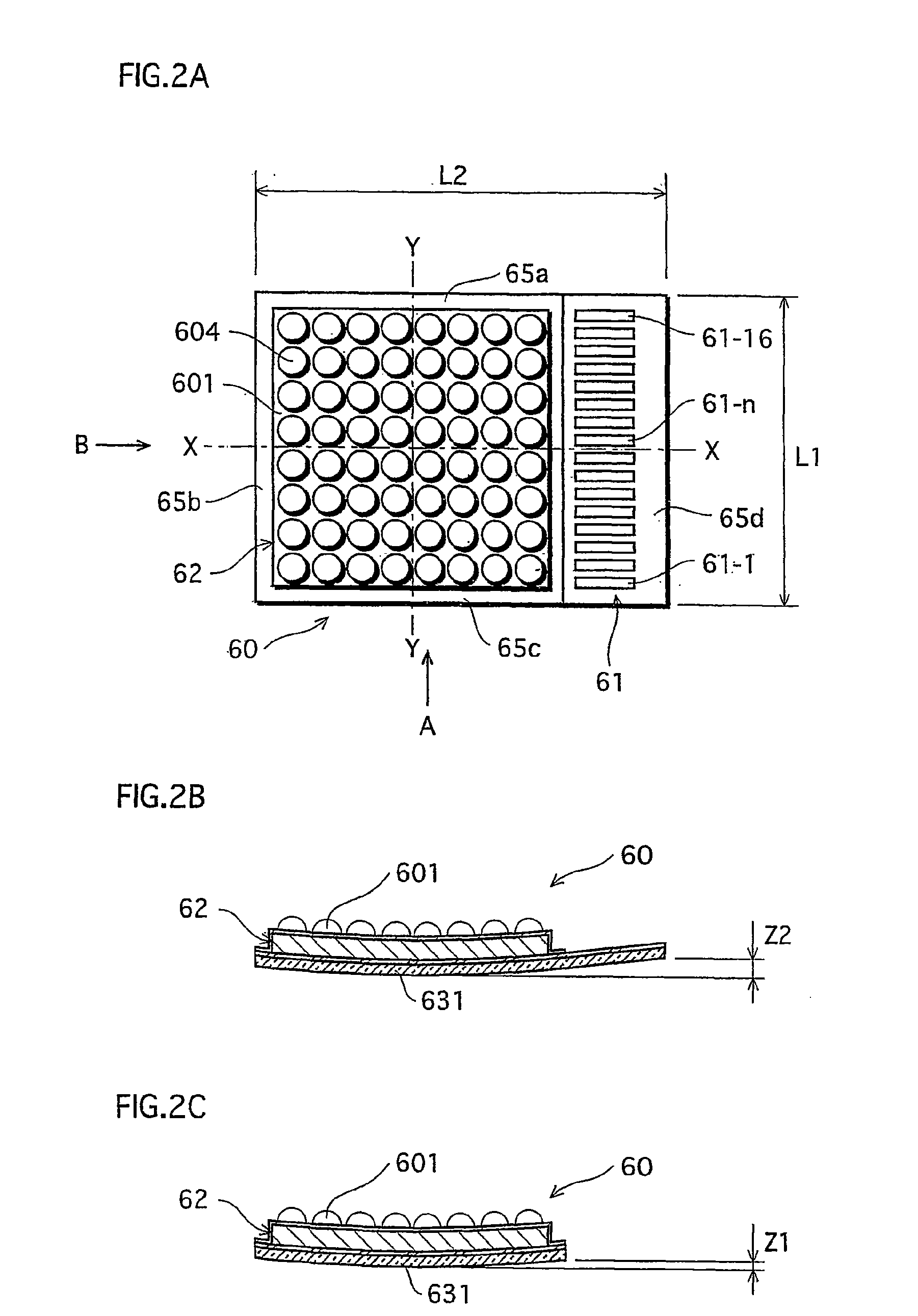
[0077]The dimensions of the LED module 60 are, as shown in FIG. 2A, as follows: a dimension L1 of the short sides is 23.5 mm, and a dimension L2 of the long sides is 28.5 mm. The metal plate 631 that composes the metal base substrate 63 is a 1 mm-thick aluminium plate, and the insulating plate 632 is 0.1 mm thick and is made of thermosetting resin that includes filler. A wiring pattern is formed on the insulating plate 632 according to etching or the like using 10 μm-thick copper foil. The resin is epoxy resin.

[0078]Each LED 6010 mounted on the metal base substrate 63 is substantially cuboid in shape, with a 0.3 mm by 0.3 mm square-shaped base and a height of 0.1 mm, and is made of an InGaN material. Each LED 6010 has a P-type electrode and an N-type electrode on a lower surface, and is flip chip mounted via a bump to a wiring pattern formed on the front surface of the insulating plate 632. Note that the LEDs 6010 are blue-light emitting LEDs, and the ...

first embodiment

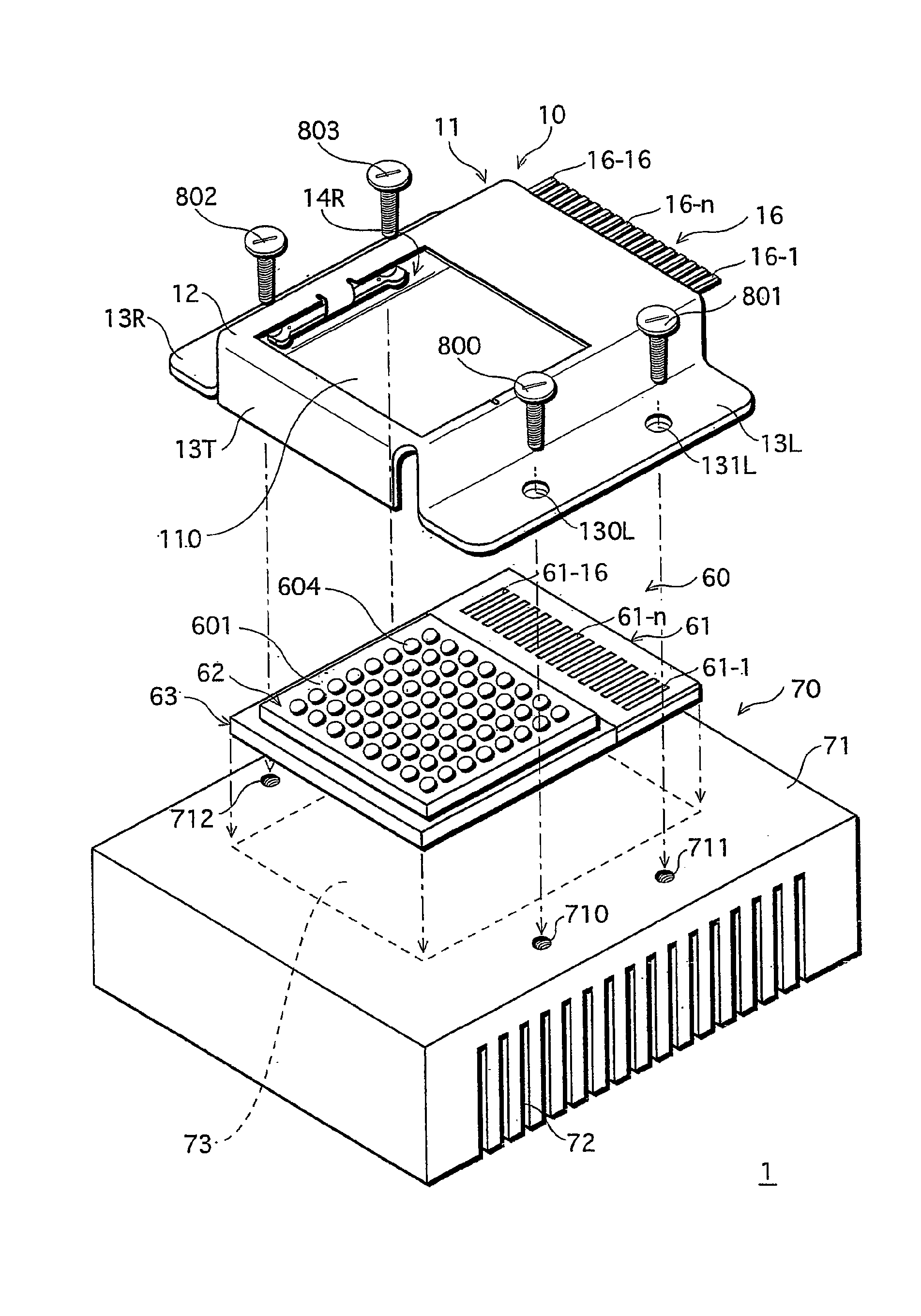
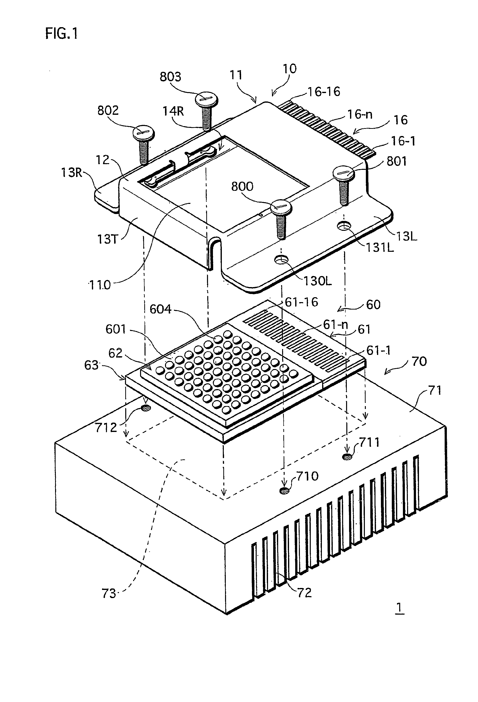
[0138]The shape of the socket 910 is essentially the same as the socket 10 in the embodiment, but it has a receiving opening 920 for receiving the light emitting module (60) which slides in to the arrangement. The receiving opening 920 is formed in the part of the socket 10 of the first embodiment that opposes power terminal unit 16, in other words, in the side of the socket that is the opposite side to the power terminal unit 16.

[0139]Pressing units that press the inserted light emitting module (60) against the heat sink 70 are provided on the sides of a cutout 925 that is on a top wall 915 of the socket and that composes the light passing unit (in other words, a total of tree places: the opposing long sides and the short side on the power terminal unit 16 side).

[0140]The socket 910 having this structure achieves substantially the same effects as the first embodiment. In other words, in the present example also, the central part of the metal plate that is the bottom side of the lig...


PUM


Abstract

A lighting device includes a heatsink 70, a socket 10 and an LED module 60. The LED module 60 has a light emitting unit 62 in a central part of a top side of a metal base substrate 63 composed of an insulating plate and a metal plate. The LED module 60 is warped such that the central part protrudes on a heatsink 70 side, which is the side opposite to the light emitting unit 62 side. The LED module 60 is mounted on the heatsink 70 in a state of the surrounds of the light emitting unit 62 being pressed according to pressing units 14T, 14L, and 14D of the socket 10. Pressing the surrounds of the light emitting unit 62 against the heatsink 70 ensures that a central part of the warping of the LED module 60 contacts the heatsink 70.

Description

TECHNICAL FIELD[0001]The present invention relates to a light emitting module that is mounted on a heatsink, and a lighting device and a display device composed of the light emitting module mounted on a heatsink by a socket.BACKGROUND ART[0002]Inventors have proposed various lighting devices composed of an LED (light emitting) module in which light emitting units are formed on a front surface of a substrate, a heatsink, and a socket for mounting the LED module to the heatsink (for example, see Japanese Laid-Open Patent Application No. 2004-265626 and Japanese Laid-Open Patent Application No. 2004-265619).[0003]The substrate of an LED module is composed of an insulating plate and a metal plate (heat conducting plate) layered together, and the light emitting unit is composed of a plurality of LEDs that are mounted in a central area of the front surface of the insulating plate. The metal plate ensures stiffness of the LED module as well as having a function of conducting heat generated...

Claims


Application Information

Patent Timeline
Patent Type & Authority Applications(United States)
IPC IPC(8): F21V29/00F21V19/00H01L33/54H01L33/56H01L33/60H01L33/64
CPCF21V19/0055F21V29/004F21Y2101/02H05K1/0203H05K3/0061H05K2201/09018F21V29/763H01L2224/48091H01L2224/73265H05K2201/10106Y10S362/80F21Y2105/001H01L2924/00014F21Y2105/10F21Y2115/10
Inventor MATSUI, NOBUYUKINAGAI, HIDEONISHIMOTO, KEIJIOGATA, TOSHIFUMI
Owner SATCO PRODS
Why Eureka
Try Eureka