Vehicle Lighting Unit and Vehicle Light

a technology for vehicle lighting and vehicle lights, which is applied in fixed installation, lighting and heating apparatus, and support devices for lighting, etc., can solve the problems of low light utilization efficiency, poor visibility of vehicle headlight units in the depth direction, and inability to obtain thin depth direction of vehicle headlight units, etc., and achieve high light utilization efficiency and high brightness

Active Publication Date: 2010-02-25
STANLEY ELECTRIC CO LTD
View PDF2 Cites 45 Cited by
  • Summary
  • Abstract
  • Description
  • Claims
  • Application Information

AI Technical Summary

Benefits of technology

[0012]The vehicle lighting unit configured as described above uses the direct light of the LED light source with high brightness for forming a light distribution pattern. Accordingly, the first reflecting surface and the second reflecting surface can be formed to be relatively short in the depth dimension in the optical axis direction, and for example, short enough for the reflecting surfaces to reflect light from the LED light source while the light utilization efficiency of the LED light source can be maintained high. Furthermore, the length of the first reflecting surface and that of the second reflecting surface can be made shorter in the optical axis direction than the reflecting surface of the conventional vehicle lighting unit since the vehicle lighting unit of the presently disclosed subject matter uses the direct light of the LED light source with high brightness for forming a light distribution pattern. This configuration can allow the profile of the entire vehicle lighting unit in the depth direction to be thinner.
[0015]According to the presently disclosed subject matter, the optical member can further include a third reflecting surface that is opposite to the first reflecting surface with the optical axis of the LED light source being interposed therebetween and substantially parallel with the optical axis of the LED light source. The third reflecting surface can cover the area where light that is obliquely and upwardly emitted from the LED light source is projected, the light having conventionally been wasted. Accordingly, the light can be utilized for forming the second light distribution pattern portion, thereby improving the light utilization efficiency.
[0023]According to the presently disclosed subject matter, the light emitting portion of the LED light source can have a lower side that is disposed such that the first reflecting surface can prevent light from the light emitting portion from entering below the first reflection surface.
[0027]As described above, a vehicle lighting unit and a vehicle light made in accordance with principles of to the presently disclosed subject matter can effectively utilize the direct light emitted from the LED light source in the optical axis direction with high brightness, for forming a light distribution pattern. Accordingly, even when the dimension of the first reflecting surface and the second reflecting surface in the optical axis direction is shortened enough for them to reflect the light from the LED light source, the vehicle lighting unit can maintain the light utilization efficiency high. Furthermore, the profile of the vehicle lighting unit in the depth direction can be thinned.

Problems solved by technology

In other words, a vehicle headlight unit thin in the depth direction cannot be obtained due to the required dimension of the reflecting surface.
Also the far visibility by the light distribution deteriorates due to this, and no clear light / dark border (or so-called “cut-off line” can be formed in the light distribution pattern.

Method used


Image

  • Vehicle Lighting Unit and Vehicle Light
  • Vehicle Lighting Unit and Vehicle Light
  • Vehicle Lighting Unit and Vehicle Light

Examples


Embodiment Construction

[0046]A description will now be made below with respect to certain exemplary embodiments of a vehicle lighting unit of and vehicle light made in accordance with principles of the presently disclosed subject matter and with reference to the accompanying drawings. Hereinafter, the exemplary embodiments of the vehicle lighting unit will be described as a vehicle headlight unit.

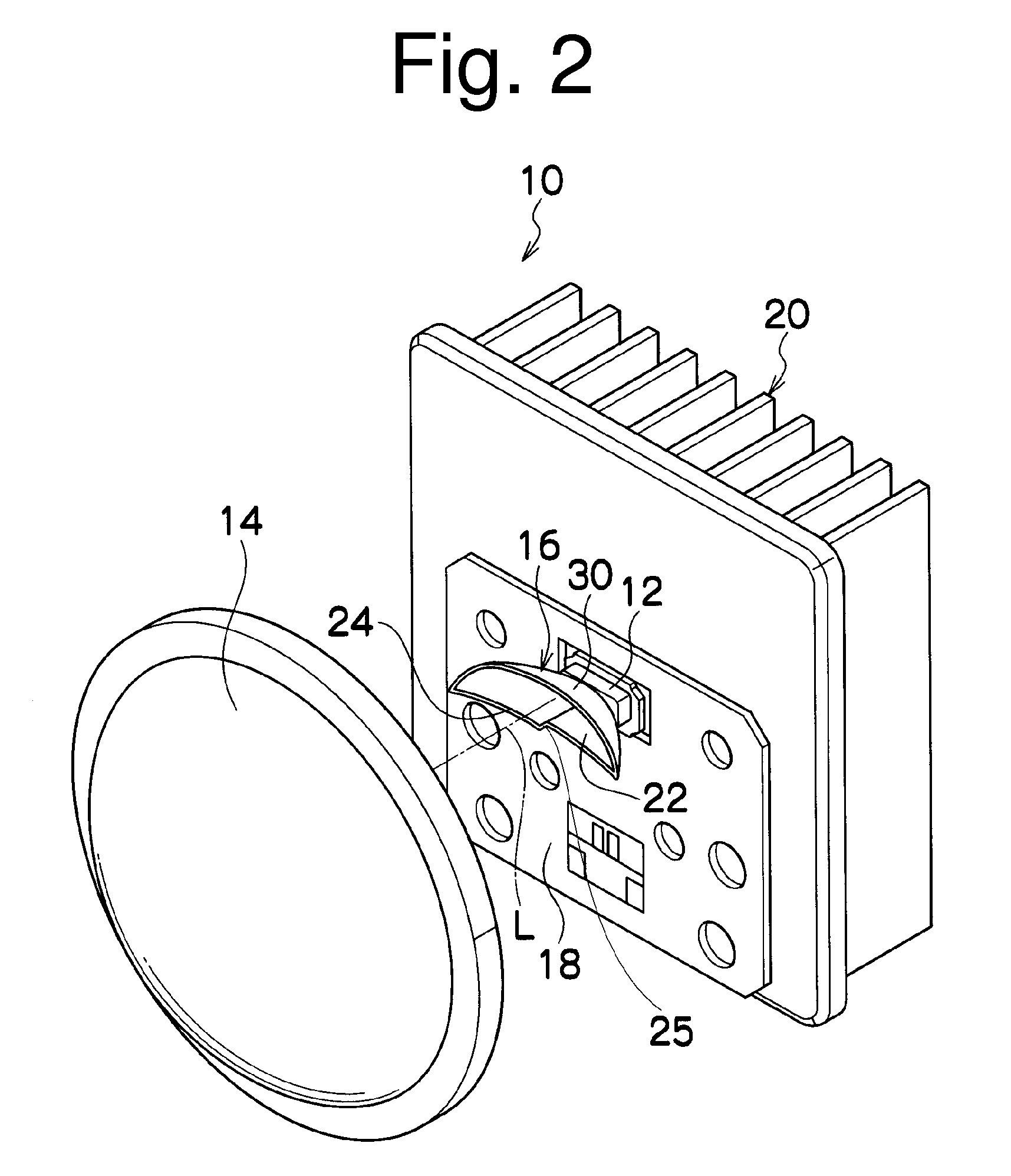
[0047]FIG. 2 is a perspective view illustrating a vehicle headlight unit 10 of a first exemplary embodiment, and FIG. 3 is a side view of the vehicle headlight unit 10.

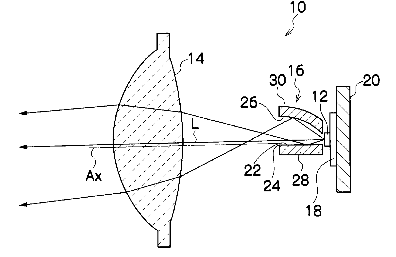
[0048]The vehicle headlight unit 10 can include an LED light source 12, a projection lens 14, and an optical member 16 disposed between the LED light source 12 and the projection lens 14.

[0049]The LED light source 12 has an optical axis L which substantially coincides with the optical axis Ax of the vehicle headlight unit 10 (see FIG. 5). The LED light source 12 can include an LED chip (or LED chips) (not illustrated) that can emit light configured...


PUM


Abstract

A vehicle lighting unit can include a first reflector surface and a second reflector surface disposed vertically with the optical axis of an LED light source interposed therebetween. The first reflecting surface and the second reflecting surface can form respective light distribution patterns. The first reflecting surface can include an edge near the projection lens formed in a substantially elliptic shape and designed so as to take an aberration of the projection lens into consideration. The edge can be disposed so as to coincide with a focus group of the projection lens. The second reflecting surface can be formed to have a substantially conical curved surface or a curved surface having at least a part of a cross section of a substantially conical curved surface. Direct light emitted from the LED light source and passing through / between the first reflecting surface and the second reflecting surface can form a light distribution pattern.

Description

[0001]This application claims the priority benefit under 35 U.S.C. §119 of Japanese Patent Application No. 2008-211980 filed on Aug. 20, 2008, which is hereby incorporated in its entirety by reference.TECHNICAL FIELD[0002]The presently disclosed subject matter relates to a vehicle lighting unit and a vehicle light, and in particular, to a vehicle lighting unit using an LED light source and a vehicle light including the vehicle lighting unit.BACKGROUND ART[0003]Conventionally known vehicle lights, in particular, vehicle headlights can form a desired light distribution pattern by superposing, on a basic light distribution pattern, at least one additional light distribution pattern using at least two reflecting surfaces (see, for example, Japanese Patent Application Laid-Open No. 2003-317513). An exemplary vehicle headlight of this type can have an LED light source, a first reflecting surface for reflecting light from the LED light source to form a basic light distribution pattern, and...

Claims


Application Information

Patent Timeline
Patent Type & Authority Applications(United States)
IPC IPC(8): B60Q1/00
CPCF21S48/1154F21S48/1159F21S48/1388F21S48/328F21V5/04F21S48/1329F21V13/04F21V29/004F21Y2101/02F21S48/1258F21V7/0091F21V29/74F21Y2115/10F21S41/143F21S41/255F21S41/285F21S41/321F21S41/322F21S41/36F21S41/365F21S41/43F21S45/47
Inventor YATSUDA, YASUSHI
Owner STANLEY ELECTRIC CO LTD
Why Eureka
Try Eureka