Magnetic Stirring Devices and Methods

a technology of magnetic stirring and magnetic field, applied in the direction of mixing, permanent magnets, mixers, etc., to achieve the effects of improving the stability of magnetic stirring elements, improving the stirring efficiency, and improving the magnetic field coverage and/or the magnetic field/strength

Inactive Publication Date: 2010-02-25
TIEN LINSHENG WALTER +2
View PDF22 Cites 65 Cited by
  • Summary
  • Abstract
  • Description
  • Claims
  • Application Information

AI Technical Summary

Benefits of technology

[0009]The present invention attempts to address this need, as well as other needs and problems associated with existing and previously described magnetic stirring devices. The present magnetic stirring devices include magnetic stirring elements, such as stirrer bars and the like, and magnetic stirring systems, such as stirrer plates and the like. In one contemplated embodiment, the present magnetic stirring devices provide improved stirring efficiency and improved stability of magnetic stirring elements by improving the magnetic field coverage and/or the magnetic field/strength compared to existing magnetic stirring elements/systems. In another embodiment, stirring efficiency is improved by having improved torque in the contemplated stirring plate and/or stirring element. With the improved stability, the present magnetic stirring devices are able to stir or mix compositions comprising two or more different phases more efficientl

Problems solved by technology

Although a number of magnetic stirring devices, including magnetic stirring elements and magnetic stirrer plates, have been described and are publicly available, existing magnetic stirring elements frequently “spin out”, especially at high speeds of rotation and/or when stirring viscous compositions

Method used


Image

  • Magnetic Stirring Devices and Methods
  • Magnetic Stirring Devices and Methods
  • Magnetic Stirring Devices and Methods

Examples


Embodiment Construction

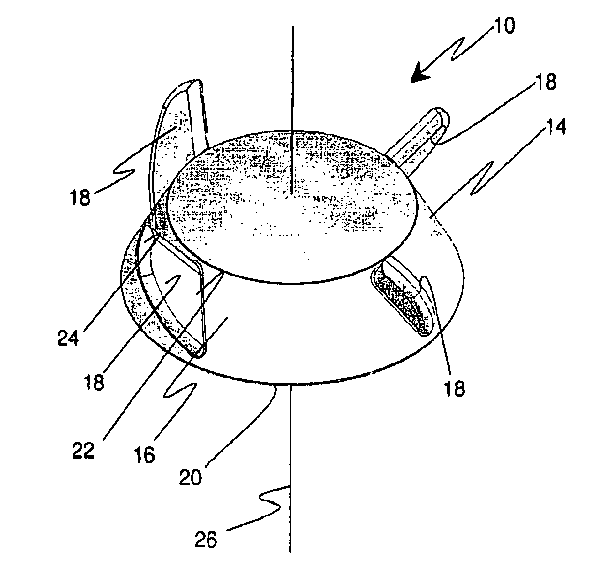
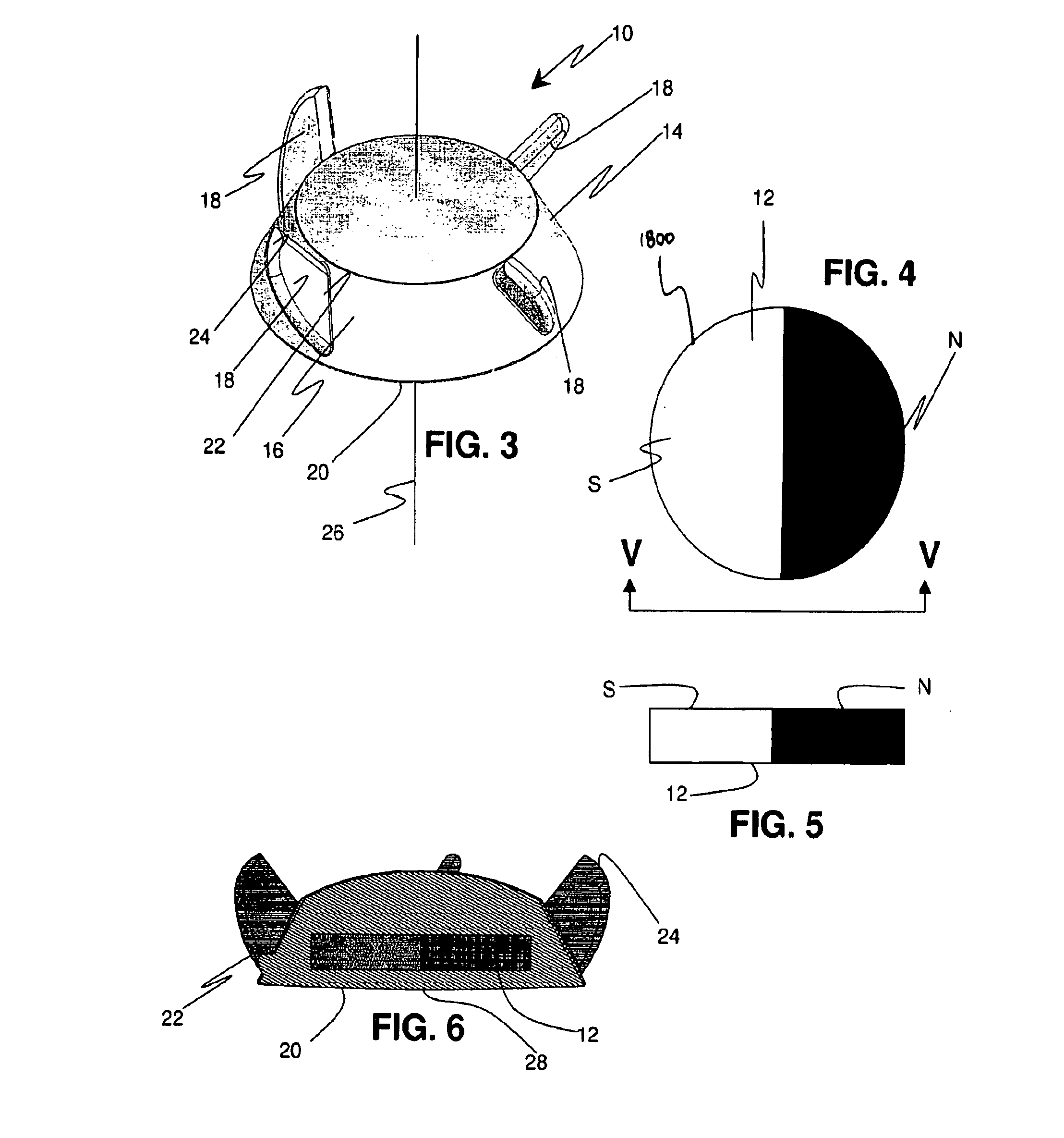
[0084]The size of the magnet, the shape of the magnet, the orientation of the poles, and the size of the housing can influence the magnetic field coverage of the magnetic stirring element and contribute to poor vortexing or mixing of liquid containing compositions, especially compositions with medium to high viscosities. A traditional stirring element having a magnetic bar in the housing only covers a horizontal line magnetic field, such that, the bar magnet has a direction of magnetism parallel to its length. The stirring or rotation of the stirring element, and the stirring stability of the stirring element, depends upon the rotation speed of the actuatable magnet of the stirrer plate.

[0085]The spinning out associated with existing magnetic stirring devices may be due to the torque in the magnetic field, area of field distribution, a total magnetic field coverage angle of the stirring element, the total magnetic field coverage angle of the actuator magnet, the speed at which the a...


PUM


Abstract

Magnetic stirring devices, such as magnetic stirring elements and magnetic stirring systems, and stirring methods where enhanced stability and mixing efficiency is made possible by using magnets that are magnetized through thickness in relation to the rotation axis so as to improve torque and magnetic field coverage. In addition, stirring elements having protruding structures such as blades and support legs are used to improve stirring efficiency.

Description

CROSS-REFERENCE TO RELATED APPLICATIONS[0001]This application claims priority to pending application PCT / US08 / 53302 filed on Feb. 7, 2008 which claims priority to U.S. Provisional Pat. No. 60 / 888,941, filed on Feb. 8, 2007, and U.S. Provisional Pat. No. 60 / 941,687, filed Jun. 3, 2007, all of which are hereby incorporated by reference in their entirety. Although incorporated by reference in its entirety, no arguments or disclaimers made in the parent applications apply to this application. Any disclaimer that may have been included in the specification of the above-referenced applications is hereby expressly rescinded.FIELD OF THE INVENTION[0002]The present invention relates generally to magnetic stirring devices and methods. More particularly, the invention relates to magnetic stirring elements (to which the inventors call the “stir-free” stirring element), and magnetic stirring systems (to which the inventors call the “spin-free” stirring system), and methods that are effective in ...

Claims


Application Information

Patent Timeline
IPC IPC(8): B01F13/08
CPCB01F13/0818H01F7/02B01F13/0827B01F33/452B01F33/453B01F2101/23
Inventor TIEN, LINSHENG WALTERMANESIS, NICK J.HUANG, GENE H.
Owner TIEN LINSHENG WALTER
Why Eureka
Try Eureka