
Antenna-aware method for transmitting packets in a wireless communication network

a wireless communication network and antenna-aware technology, applied in the field of wireless communication networks, can solve the problems of reducing spatial reuse, affecting the ability of nodes to obtain and interpret beamforming mode and antenna pattern, and affecting the effect of broadcasting to all neighbors via omni-directional antennas

Active Publication Date: 2010-02-25
ARRIS ENTERPRISES LLC
View PDF13 Cites 89 Cited by
  • Summary
  • Abstract
  • Description
  • Claims
  • Application Information

AI Technical Summary

Problems solved by technology

However, if some nodes employ advanced antenna techniques, such as beamforming, to improve link rates or extend range, the advertisements broadcast to all neighbors via omni-directional antennas may not reach all of the neighbors that could be impacted by the beamforming-based data transmission.
For the advertisement of scheduled transmissions where the broadcasting node is neither the sender nor the receiver (SMA interference reports), it is not practical for the node to obtain and interpret the beamforming mode and antenna pattern for the scheduled transmission.
The drawback is that it could significantly reduce spatial reuse.

Method used


Image

  • Antenna-aware method for transmitting packets in a wireless communication network
  • Antenna-aware method for transmitting packets in a wireless communication network
  • Antenna-aware method for transmitting packets in a wireless communication network

Examples


first embodiment

[0043]FIG. 6 is a flowchart illustrating the operation 600 of a node within a wireless communication system for advertisement of a scheduled transmission, in accordance with a As illustrated, the operation begins with Step 605 in which an originator node of a scheduled transmission determines whether or not its transmit antenna mode is omni-directional. When its transmit antenna mode is omni-directional, the operation continues to Step 610 in which the node broadcasts its schedule omni-directionally. Next, in Step 615, the originator node determines whether or not its receive antenna mode is omni-directional. When its receive antenna mode is not omni-directional, the operation continues to Step 620 in which the originator node re-broadcasts the transmission schedule on one or more transmitter beams that are reciprocal to those that will be used for directional reception. Next, and when the receive antenna mode is omni-directional, the operation ends.

[0044]Returning to Step 605, whe...

third embodiment

[0051]FIG. 8 is a flowchart illustrating the operation 800 of a node within a wireless communication system for advertisement of a scheduled transmission, in accordance with a As illustrated, the operation begins with Step 805, in which an originator node determines whether or not its transmit antenna mode is omni-directional. When its transmit antenna mode is not omni-directional, the operation continues to Step 810 in which the originator node broadcasts its schedule directionally on all available transmit beams. The operation then ends. Alternatively, when its transmit antenna mode is omni-directional in Step 805, the operation continues to Step 815 in which the originator node broadcasts its schedule omni-directional. The operation then ends.

[0052]It will be appreciate that although only one iteration of the operation is described in FIG. 8, the operation described herein can be periodically performed within one or more nodes in a wireless communication network.

[0053]In this th...


PUM


Abstract

A method for transmitting packets in a wireless communication network includes taking into consideration an antenna mode prior to transmission. The method includes determining a transmit antenna mode for a transmission between the node and at least one other node; when the transmit antenna mode is omni-directional, broadcasting a transmission schedule for the transmission omni-directionally; and when the transmit antenna is beamforming directional, broadcasting a transmission schedule for the transmission directionally on one or more transmitter beams. The method optionally can also take into consideration an antenna mode of a receive antenna between the node.

Description

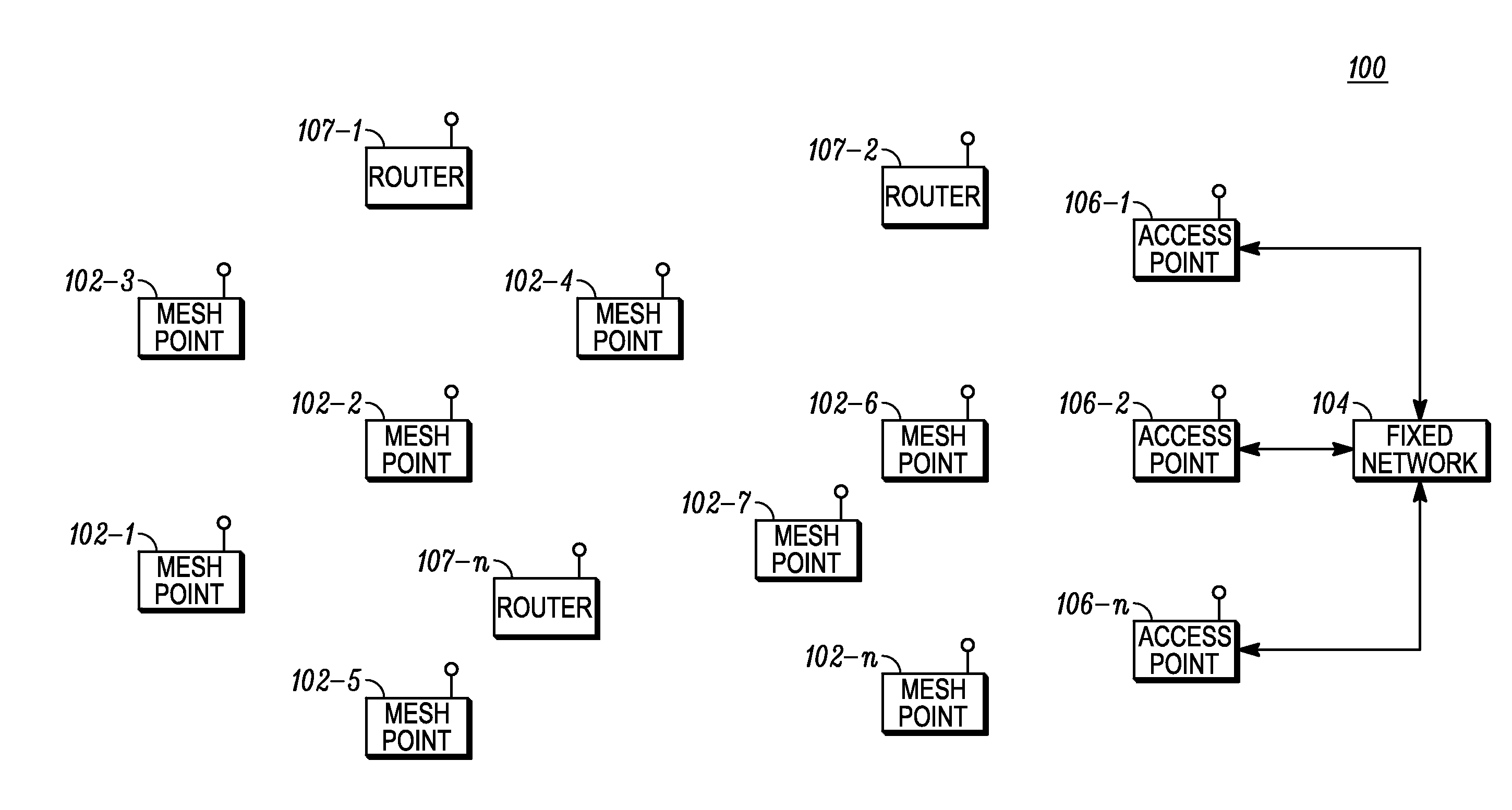
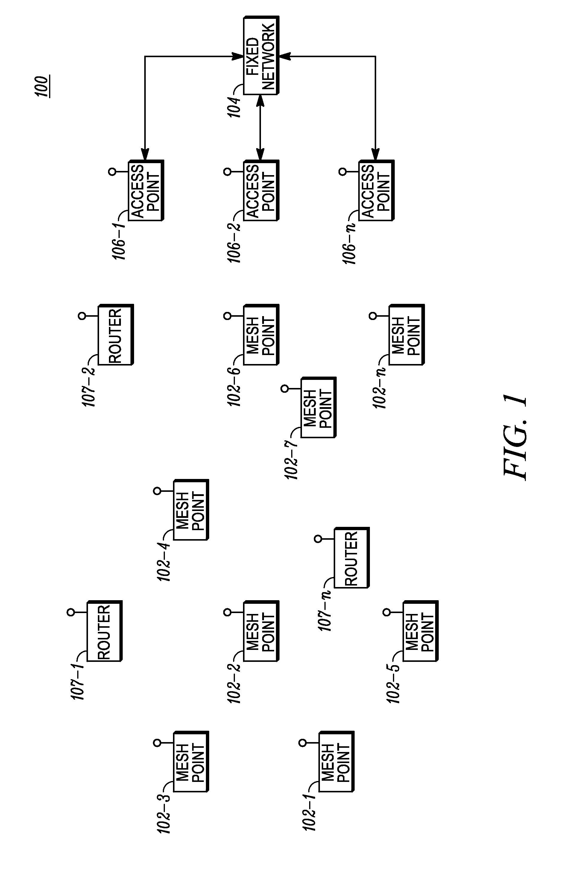
FIELD OF THE DISCLOSURE[0001]The present disclosure relates generally to wireless communication networks and more particularly to an antenna-aware method to transmit packets in a Wireless Communication Network.BACKGROUND[0002]A Wireless Local Area Network (WLAN) is a Local Area Network (LAN) that employs wireless communication such as radio frequency (RF) or infrared (IR) transmission. A WLAN typically comprises fixed-location transceivers known as access points (APs) to which client devices connect via RF technology. The access points typically are hard wired to switches and routers that interconnect them and provide access to servers. The APs are fitted with radio transceivers and omnidirectional antennas. The client transceivers, or network adapters, may be in the form of Personal Computer Memory Card International Association (PCMCIA) cards, for example. The APs are located at central points where there is good line of sight (LOS) to the client devices and link quality, therefor...

Claims


Application Information

Patent Timeline
Patent Type & Authority Applications(United States)
IPC IPC(8): H04Q7/00
CPCH04W48/08H04W4/06H04W72/1278H04W72/20H04B7/0617H04B7/155H04W40/06
Inventor CHEN, YEEMEOTT, STEPHEN P.MAKHLOUF, ISAM R.
Owner ARRIS ENTERPRISES LLC
Learn More