
Decoding system for executing accelerated processing in real time and related methods

Inactive Publication Date: 2010-02-25
PIXTREE TECH
View PDF5 Cites 12 Cited by
  • Summary
  • Abstract
  • Description
  • Claims
  • Application Information

AI Technical Summary

Benefits of technology

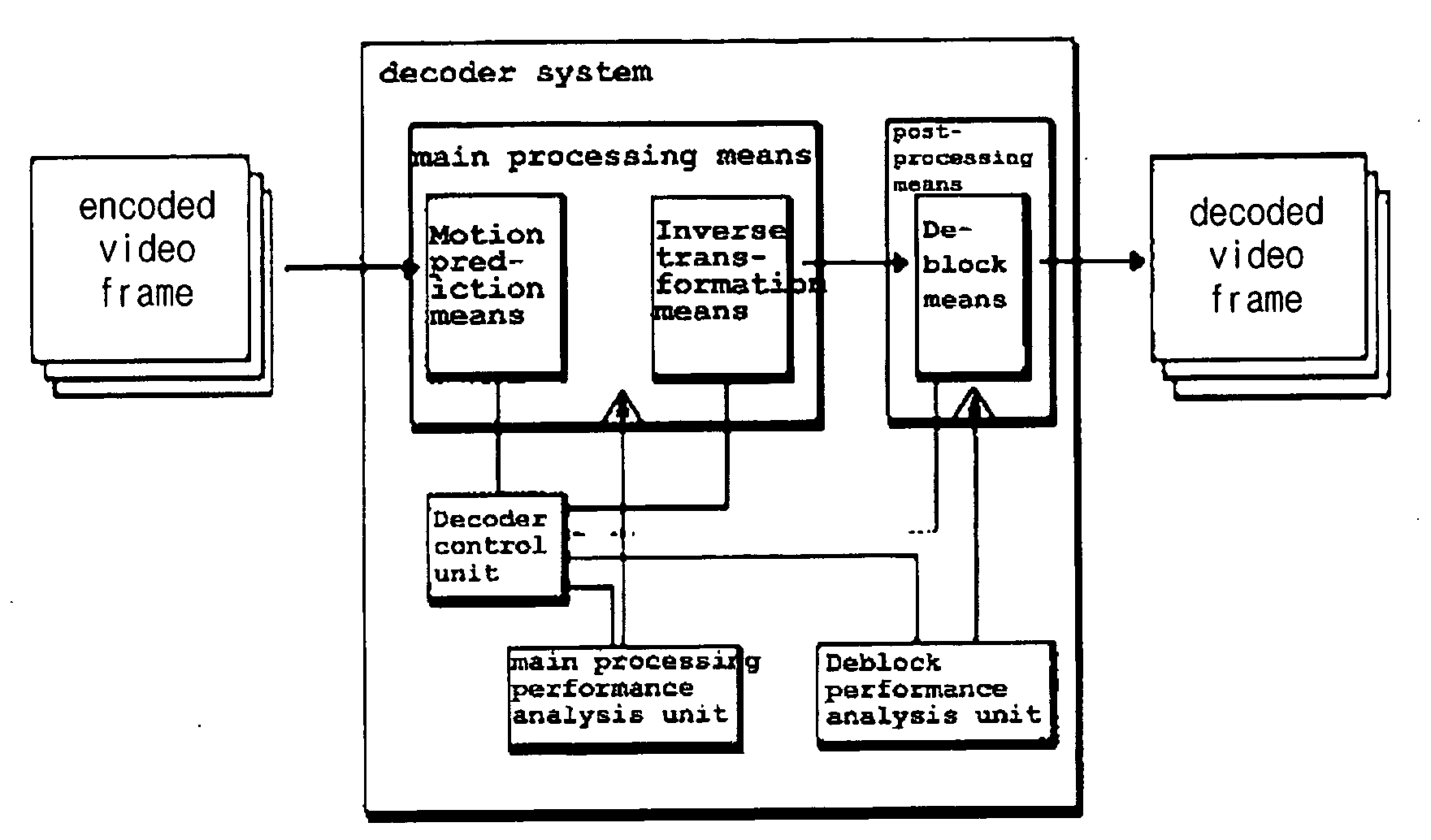
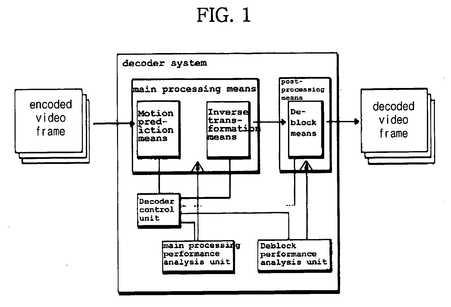
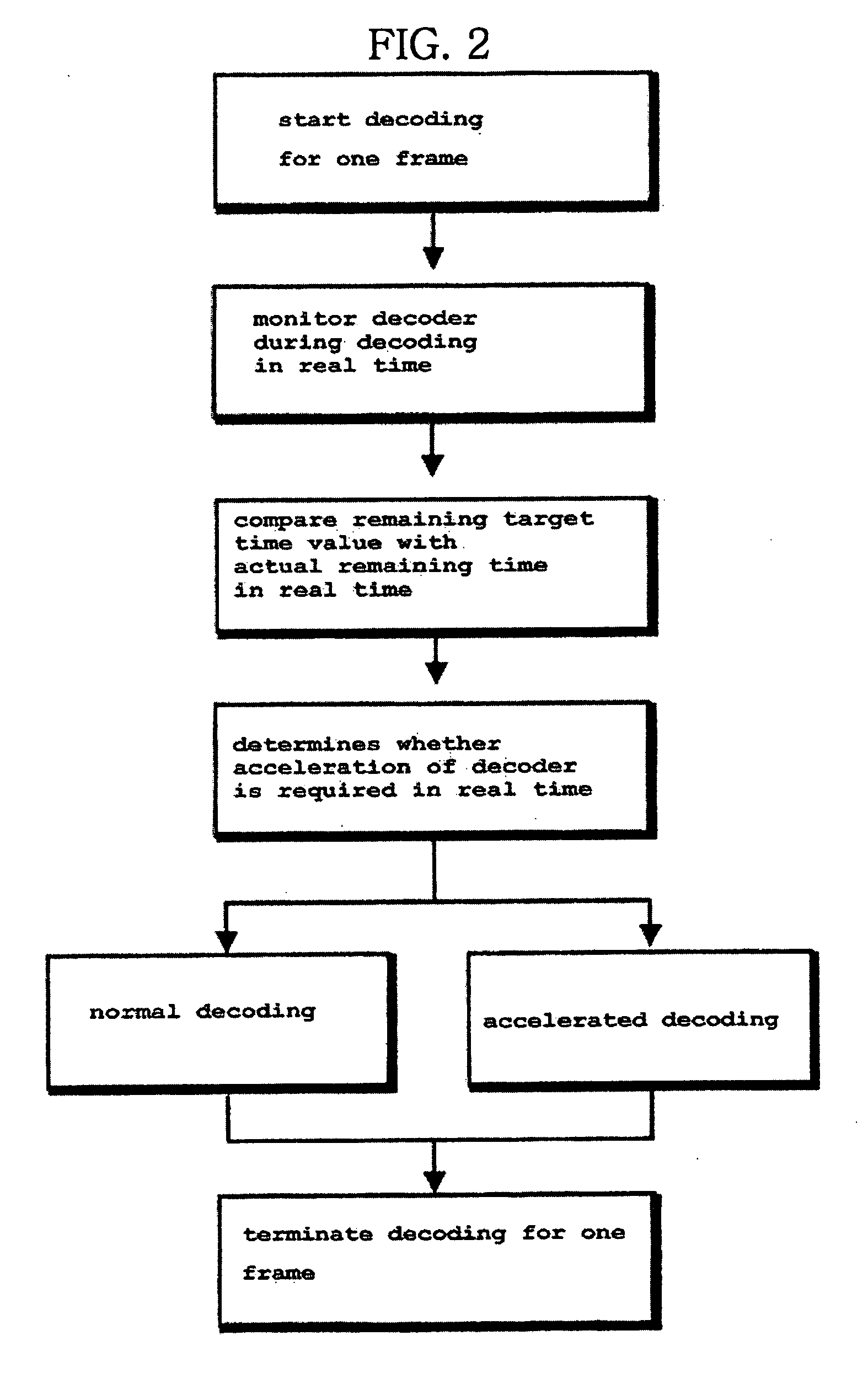
[0010]The present invention relates to a method and system which monitor respective means needed for decoding in real time at the time of decoding video frames, analyze the respective performance thereof and determine means to be accelerated by a decoder control unit, and a method for the acceleration, based on the analysis, thereby smoothly reproducing a moving picture without omitting any frames.
[0011]Even if the hardware performance of a decoding terminal is insufficient, the user of the present invention is advantageous in that a moving picture is smoothly and acceptably reproduced without serious degradation of picture quality.
[0012]In detail, the present invention analyzes the performance time of a terminal decoder in real time, simplifies and selectively omits calculation steps in ascending order of degradation in picture quality in consideration of the status of a processor, based on the analysis, thereby enabling a natural moving picture service at optimal picture quality for a given level of performance even under the condition of restricted performance resources.
[0013]Even in a system environment in which the ability to reproduce a moving picture at a uniform frame rate is slightly insufficient, or the amount of processing is large, the present invention actively deals with given conditions, so that there is an advantage of ensuring smooth reproduction of a moving picture. As a result, the present invention has advantages of improving and stabilizing picture quality in a video terminal and simultaneously guiding and controlling effective distribution and application of system resources. When the video terminal distributes the system resources to respective modular function units, such as an audio unit, a video unit, a user interface unit, a screen display unit, and a system control unit, and controls them, the present invention effectively restricts a decoder unit, thereby enabling the effective control of the other functional units.
[0014]Experimental values representing the advantages of the present invention are illustrated in FIG. 9.
[0015]FIG. 9 illustrates a comparison of the number of frames decoded per unit time by a decoder to which the algorithm of the present invention is applied with that of a general decoder on the assumption that the rate of input data is the same as the frame rate of video signals, that is, 15 frames per second (15 fps). If decoding can be performed faster than 15 frames per second, a picture that is identical to an original picture restored through a normal decoding procedure can be acquired. In contrast, if not, various means proposed in the present invention are employed, so that a video picture is restored at the originally intended frame rate such that deterioration of picture quality is minimized and the calculation time is reduced.

Problems solved by technology

If an interval of time longer than a tolerable limit is taken for the restoration of any one specific frame, the terminal system cannot display a corresponding scene on a screen in time, or the picture quality and reproduction of subsequent frames are affected thereby.
However, the reproduction based on decoding in which some frames are omitted creates an unpleasant feeling due to discontinuous upon scene changes or the serious distortion of pictures.
As described above, a conventional video decoder or a video terminal generally omits a corresponding frame or replaces the frame with a previously restored frame at the time at which a problem occurs without using a separate solution when a picture is not restored within a reference time because the performance of such a system does not reach a desired level or the performance of the terminal is limited in a specific environment, so that a problem occurs in that relatively poor picture quality results.

Method used


Image

  • Decoding system for executing accelerated processing in real time and related methods
  • Decoding system for executing accelerated processing in real time and related methods
  • Decoding system for executing accelerated processing in real time and related methods

Examples


first embodiment

Acceleration of Deblock Filtering

[0053]One of the representative embodiments of the present invention is a method using accelerated filtering at a deblock filtering step. The reason for this is that the deblock filtering requires a large amount of computational work and affects picture quality somewhat less than the other restoring steps.

[0054]The example of implementation and application of H.264, which is an example of the present invention, is described. First, the decoder control unit receives a target time value Tf,th taken to decode a frame, or calculates it by oneself. In this case, “provision” means the state in which the decoder control unit has the target time value, and is used to include that a predetermined value is provided from another device and that it is obtained from its own statistical data or through calculation.

[0055]Thereafter, the inverse transformation and the motion prediction and compensation are performed on the partial frames of a frame to be currently d...

second embodiment

Acceleration Method 1 of Partial Frames

[0062]When the available time of a processor is insufficient in spite of the acceleration of the deblock filtering, a more powerful means must be additionally provided, which also takes into account that the degree of deterioration of picture quality increases. For example, when it is determined that during performance of decoding on a certain partial frame prior to deblock filtering, time actually taken up to the certain frame exceeds a time limit which should be taken up to the certain frame, the acceleration step is necessarily performed on partial frames subsequent to the certain frame.

[0063]This process is described in detail below.

[0064]A step of providing a first target time value, which the decoder control unit can take to decode one video frame, is performed before and after the start of decoding for a specific frame. The first target time value Tf,th is the total time that can be taken for the main processing and the post-processing a...

third embodiment

Acceleration Method for Partial Frames

[0077]Another method for acceleration of main processing is to compare time taken for partial frames up to the current time with an available time value at the above-described comparison step, rather than comparing time required for subsequent partial frames.

[0078]In more detail, a step of receiving a first target time value, a step of obtaining a second target time value and a step of calculating an average main processing time value are the same as or similar to that of the second embodiment. Furthermore, the step at which the main processing means performs the main processing step for predetermined frames of the video frames and, at the same time, the main processing performance analysis unit monitors the performance of the main processing means and notifies the decoder control unit of it, is a single step.

[0079]A characteristic feature is the performance of a step in which the decoder control unit calculates the value of the main processing ...


PUM


Abstract

A method of operating a video decoder system includes decoding an encoded video frame using a decoder control unit for determining whether the acceleration is required for respective decoding functional units and the degree thereof. This includes the decoder control unit receiving a target time value to be taken to decode a frame; the decoder control unit performing main processing including inverse transformation and motion prediction on a predetermined frame; the deblock unit providing a value of time taken to perform deblock filtering on a frame prior to the predetermined frame to the decoder control unit; the decoder control unit comparing a value of total time taken with the target time value, in which the received value of time taken for the deblock filtering of the previous frame and the value of time taken for the main processing are added; and the decoder control unit accelerating deblock filtering of the deblock unit if it is determined that the total time taken exceeds the target time value at the comparison step.

Description

TECHNICAL FIELD[0001]The present invention relates, in general, to a video decoder for generating restored pictures through the decoding of video data compressed and transmitted by an encoder and reproducing them and, more particularly, to a method of simplifying a decoding process according to predetermined logic when the remaining time is shorter than the required absolute time during the monitoring of the decoding status of a decoder, thereby securing the time required for decoding, and to the structure of the decoder therefor.BACKGROUND ART[0002]Generally, only when a video decoder for decoding compressed moving pictures can restore respective frames of a moving picture to be restored within a predetermined time, a terminal system can reproduce the moving picture with smooth scene changes.[0003]If an interval of time longer than a tolerable limit is taken for the restoration of any one specific frame, the terminal system cannot display a corresponding scene on a screen in time, ...

Claims


Application Information

Patent Timeline
IPC IPC(8): H04N7/26
CPCH04N19/105H04N19/172H04N19/117H04N19/42H04N19/156H04N19/44H04N19/132H04N21/442
Inventor SHIN, JAE-SEOBRYOO, SUNG-GULSON, SE-HOONKIM, TAE-JIN
Owner PIXTREE TECH
Learn More