
Superposition coding

Inactive Publication Date: 2010-02-25
MOTOROLA MOBILITY LLC
View PDF10 Cites 137 Cited by
  • Summary
  • Abstract
  • Description
  • Claims
  • Application Information

AI Technical Summary

Benefits of technology

[0016]The invention may provide improved performance and / or facilitate operation or implementation for a communication system using superposition coding / modulation. In particular, the invention may allow reduced complexity of a receiver. For example, it may allow a receiver receiving the weakest data symbol of a superposition coded data symbol to receive this data symbol without having to perform successive interference cancellation or first determining the stronger data symbol of the superposition coded data symbol.
[0017]Specifically, the operation of the transmitter may enable or improve the receiving of the first data symbols without having to first determining the second data symbols.

Problems solved by technology

For example in multi user communication systems, the interference between different users is typically the main limiting factor for the achievable system capacity.
In such systems, there is no requirement for base stations to be coordinated and therefore users in neighboring cells will interfere with the transmissions within a given cell.
Accordingly, the average throughput of a cell is typically limited by the achievable throughput for users near the edges of the cell.
Although this approach may provide good performance in many scenarios, it is also associated with some disadvantages.
Specifically, it requires a complex receiver operation for the near receiver resulting in high complexity and high resource requirements.
In particular, the need for a complete decoding and re-encoding of the data for the far receiver before the data for the near receiver can be decoded results in a substantial complexity increase for the receiver.
This may further result in increased computational power which may increase the power consumption and reduce battery life for battery driven receivers.

Method used


Image

  • Superposition coding
  • Superposition coding
  • Superposition coding

Examples


Embodiment Construction

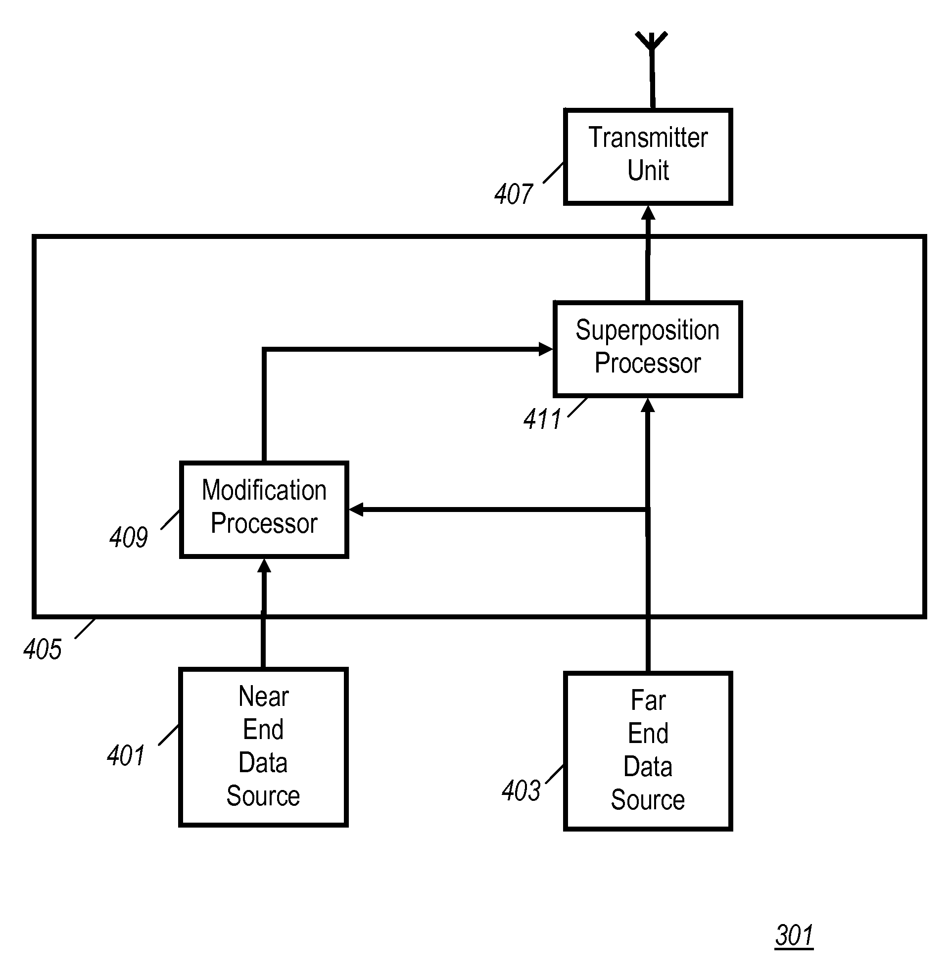
[0036]FIG. 3 illustrates an example of a communication system in accordance with some embodiments of the invention. In the example, the communication system comprises a transmitter 301 which is simultaneously transmitting data to a near receiver 303 and a far receiver 305 using superposition coding. The transmitter 301 may for example be a transmitter of a base station or an access point of a cellular communication system or a wireless network. The near receiver 303 and the far receiver may specifically be a remote station, subscriber unit, user equipment or terminal of the cellular communication system or the wireless network.

[0037]In the system, superposition data symbols are transmitted from the transmitter 301 to the near receiver 303 and the far receiver 305 with the data symbols for the near receiver 303 (henceforth the near end symbols) having lower energy than the data symbols for the far receiver 305 (henceforth the far end symbols). It will be appreciated that the manageme...


PUM


Abstract

A transmitter and receiver communicate using a modified superposition coding scheme. The transmitter transits superposition symbols which include a near end symbol for a near receiver and a far end symbol for a far receiver. The transmitter modifies the near end symbol depending on the far end symbol prior to transmission. Specifically, the near end symbol may be mirrored around the real or imaginary axis. The near receiver generates mirrored superposition symbols by applying mirroring to each received superposition symbol around at least one of the real axis and the imaginary axis in response to the value of the received symbol. The mirroring may remove the uncertainty of the far end symbol value allowing a simpler decision for the near end symbol. The mirroring performed by the transmitter and the near receiver will negate each other for the near end symbol thereby allowing a simplified near end receiver operation.

Description

FIELD OF THE INVENTION [0001]The invention relates to superposition coding and in particular, but not exclusively, to superposition coding for broadband access radio communication systems.BACKGROUND OF THE INVENTION [0002]For radio communication systems, the noise and interference performance and the spectral efficiency are some of the most critical parameters for providing high performance and a high capacity.[0003]For example in multi user communication systems, the interference between different users is typically the main limiting factor for the achievable system capacity. For example, for the next generation of broadband systems, it has been proposed to use Multiple Input Multiple Output (MIMO) schemes to reduce the interference performance. Examples of these systems include IEEE 802.16e (also known as WiMAX mobile), 3GPP Long Term Evolution (including Evolved Packet System) or 3GPP2 Ultra Mobile Broadband.[0004]In such systems, there is no requirement for base stations to be c...

Claims


Application Information

Patent Timeline
IPC IPC(8): H04L27/28
CPCH04L27/0008H04L27/3488H04L27/3472
Inventor MAZET, LAURENT S.
Owner MOTOROLA MOBILITY LLC
Features
  • Generate Ideas
  • Intellectual Property
  • Life Sciences
  • Materials
  • Tech Scout
  • Unparalleled Data Quality
  • Higher Quality Content
  • 60% Fewer Hallucinations
Learn More