
Blade drive device

Active Publication Date: 2010-02-25
SEIKO HLDG KK TRADING AS SEIKO HLDG CORP
View PDF30 Cites 2 Cited by
  • Summary
  • Abstract
  • Description
  • Claims
  • Application Information

AI Technical Summary

Benefits of technology

[0007]It is therefore an object of the present invention to provide a blade drive device which is reduced in size and has an improved shatter speed.

Problems solved by technology

However, the high-power actuator has a large size.
Thus, there is a problem that the size of the blade drive device is also increased by employing such an actuator.

Method used


Image

  • Blade drive device
  • Blade drive device
  • Blade drive device

Examples


first embodiment

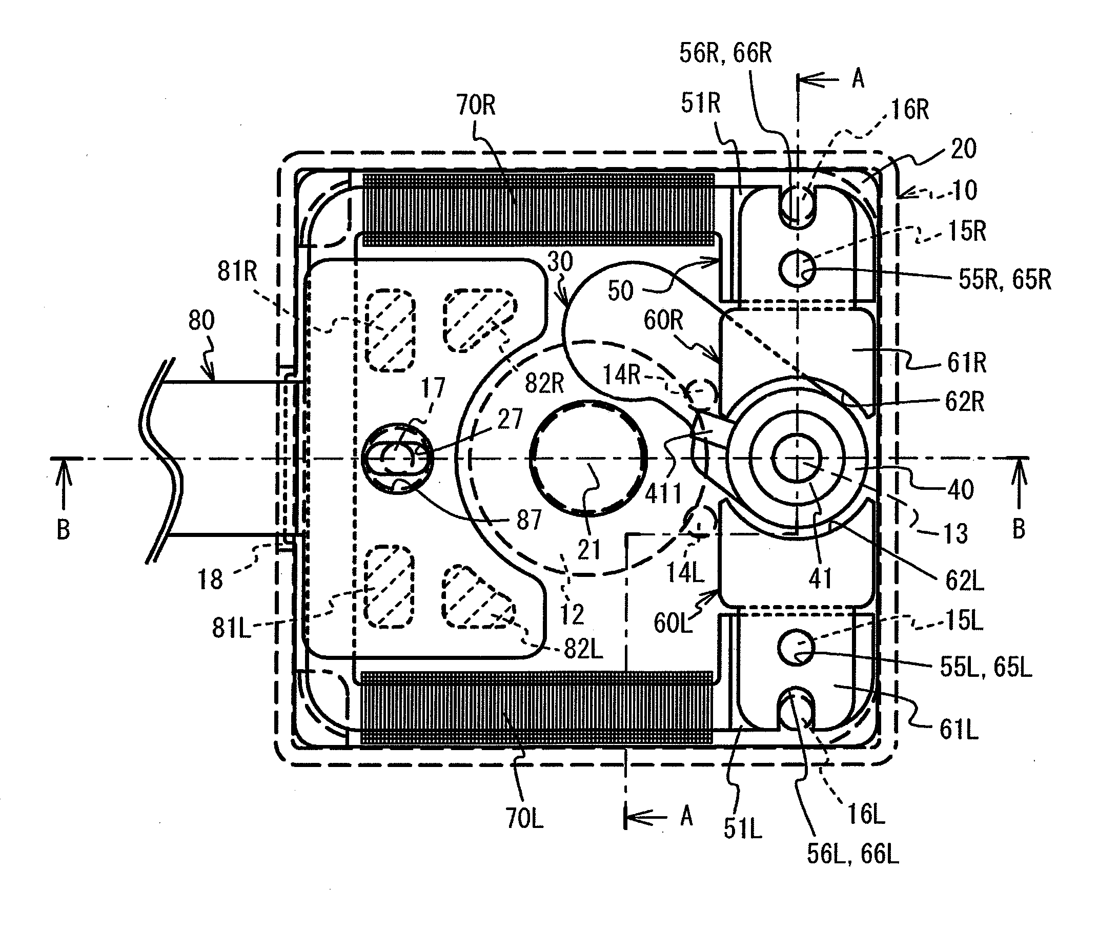
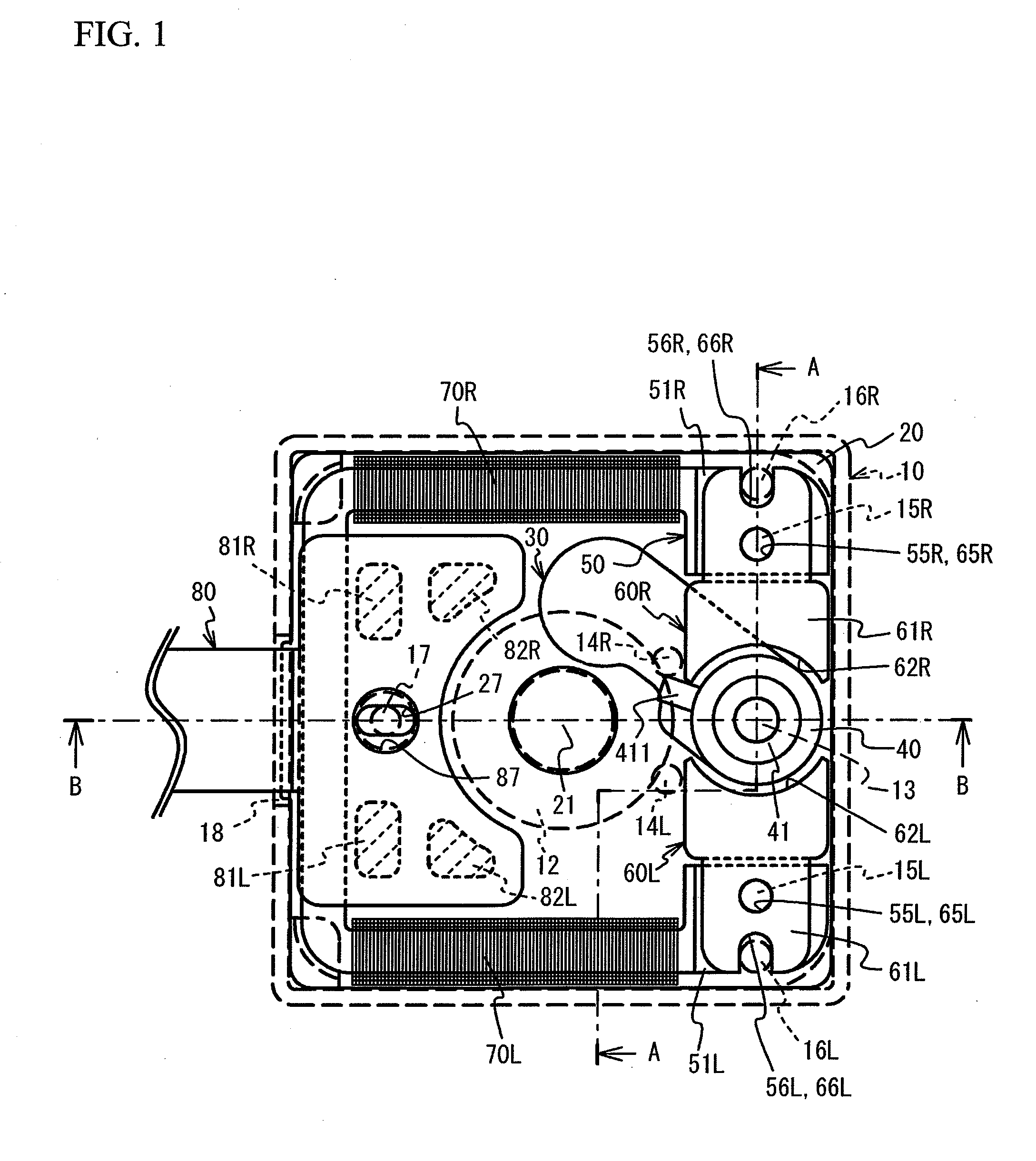
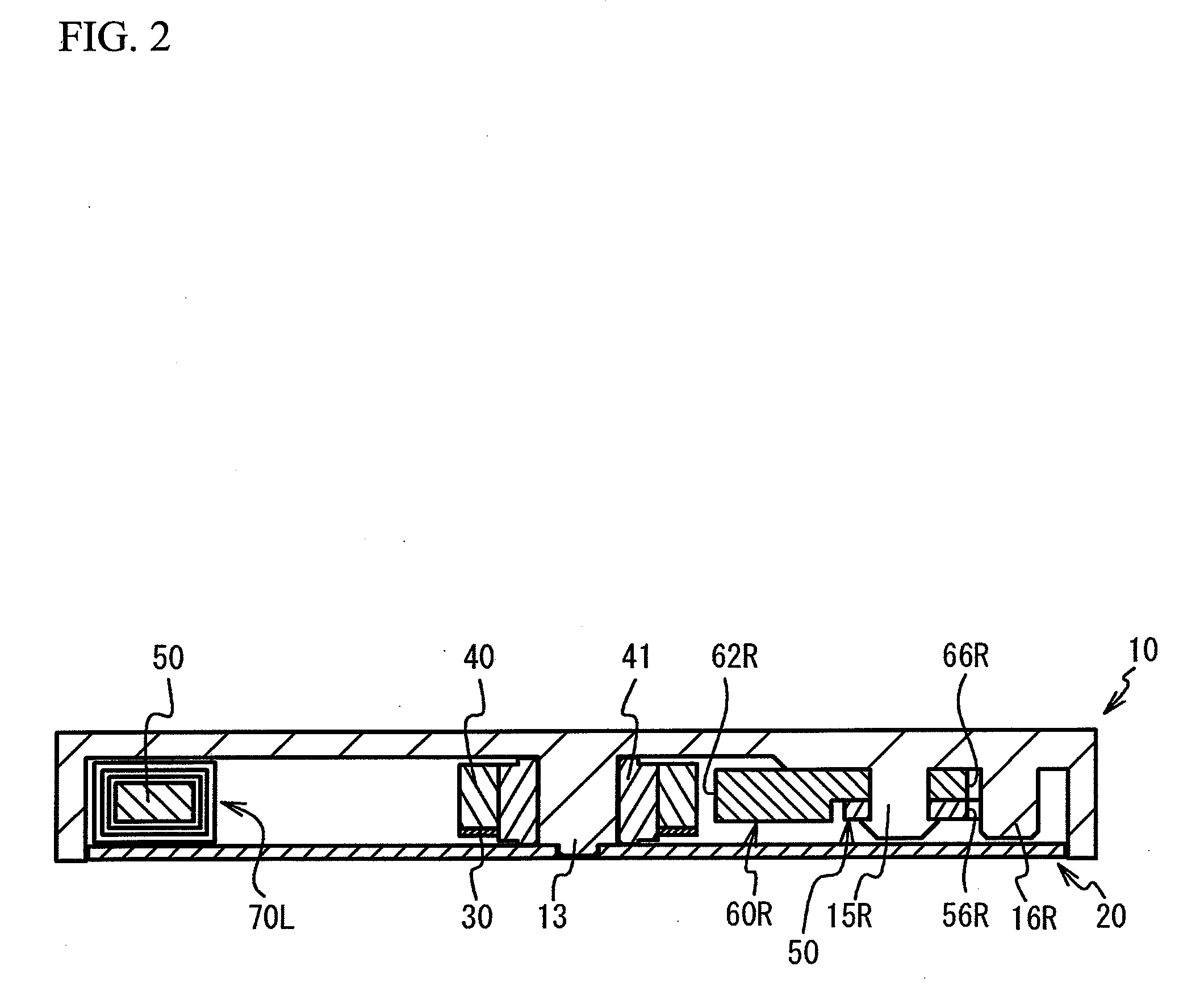
[0023]FIG. 1 is a front view of a configuration of a blade drive device according to a first embodiment. FIG. 2 is a cross-sectional view taken along a line A-A in FIG. 1. FIG. 3 is a cross-sectional view taken along a line B-B in FIG. 1. FIG. 4 is a rear view of a blade drive device according to the first embodiment. The blade drive device according to the first embodiment includes: an upper case 10; a lower case 20; a blade 30; a rotor 40; iron pieces 50, 60L, and 60R; coils 70L and 70R; and a flexible printed circuit board 80.

[0024]The upper and lower cases 10 and 20 serve as a chassis that houses the blade 30, the rotor 40, the iron pieces 50, 60L, and 60R, and a part of the flexible printed circuit board 80, as illustrated in FIGS. 2 and 3. The upper and lower cases 10 and 20 are made of a synthetic resin. The upper case 10 is thicker than the lower case 20. The blade drive device according to the first embodiment is attachable to an image pickup apparatus or a lens drive appar...

second embodiment

[0053]Next, a description will be given of a blade drive device according to a second embodiment with reference to the drawings. Additionally, in the blade drive device according to the second embodiment, components that are similar to those of the first embodiment will be denoted by the same reference numerals as used in connection with the first embodiment, and a detailed description of such components will be omitted.

[0054]FIG. 8 is a front view of a configuration of the blade drive device according to the second embodiment. FIG. 9 is a front view of the blade drive device according to the second embodiment with a flexible print substrate being omitted. FIG. 10 is a cross-sectional view taken along a line C-C in FIG. 8.

[0055]As illustrated in FIGS. 8 and 9, a rotor 40a is located at a corner portion of upper and lower cases 10a and 20a each has a rectangular shape as seen in the optical axis direction. Additionally, iron pieces 50La and 50Ra serve as a stator and each has an iden...


PUM


Abstract

A blade drive device includes: a blade; a drive source that drives the blade; and a chassis that has an opening opened and closed by the blade and that houses the blade and the drive source. The drive source includes: a rotor that is rotatably supported; a stator around which a coil for excitation is wound and which applies a rotational force to the rotor. The stator is arranged to surround a periphery of the opening and has a rectangular shape.

Description

CROSS-REFERENCE TO RELATED APPLICATION[0001]This application is a continuation of and claims priority to International Patent Application No. PCT / JP2008 / 062859 filed on Jul. 16, 2008, which claims priority to Japanese Patent Application No. 2007-233367 filed on Sep. 7, 2007, subject matter of these patent documents is incorporated by reference herein in its entirety.BACKGROUND OF THE INVENTION[0002]1. Field of the Invention[0003]The present invention relates to blade drive devices.[0004]2. Description of the Related Art[0005]Generally, a blade drive device for a camera includes: a board having an opening; a blade opening and closing the opening; and a drive source, such as an actuator, driving the blade (see Japanese Unexamined Patent Application Publication No. 2006-11293). In such a blade drive device, a high-power actuator is employed, so that a shutter speed can be increased.[0006]However, the high-power actuator has a large size. Thus, there is a problem that the size of the bl...

Claims


Application Information

Patent Timeline
IPC IPC(8): G03B9/08H02K33/00
CPCG03B9/10H02K37/16H02K33/16G03B9/02H02K1/12
Inventor MASUZAWA, KOICHIKUDO, KENICHI
Owner SEIKO HLDG KK TRADING AS SEIKO HLDG CORP
Learn More